Ventilating fan and frame structure thereof

a technology of fan frame and fan body, which is applied in the direction of non-positive displacement fluid engines, pump components, liquid fuel engine components, etc., can solve the problems that the outside flange or fixing plate of the fan frame may not fit the original installation hole on the ceiling, and achieves simplified installation steps, less spatial limitations, and facilitate the effect of installation procedur

Active Publication Date: 2020-05-05
DELTA ELECTRONICS INC
View PDF8 Cites 0 Cited by
  • Summary
  • Abstract
  • Description
  • Claims
  • Application Information

AI Technical Summary

Benefits of technology

[0034]As mentioned above, the ventilating fan of the disclosure has the movable mounting plate(s) for fixing the ventilating fan to the external structure. The mounting plates can be received in the main body or be moved through the slots to (partially) expose from the main body by rotating or sliding. According to this design, the mounting plates can be received in the main body during the installation of the ventilating fan, so that the installation can be performed in the house and suitable for most installation environments. After the ventilating fan is placed at the proper position, the mounting plates are moved to expose from the main body for fastening the entire structure of the ventilating fan. Thus, it is unnecessary to separate and assemble the fan body and fan frame structure in the installation of the ventilating fan, and the installation steps can be simplified. In addition, the design of the elastic plates and protrusions can help to precisely position the mounting plates for facilitating the installation procedure and balancing two sides of the frame structure.
[0035]Since the mounting plates are movable, the installation of the ventilating fan can have less spatial limitations. Thus, the installation or uninstallation procedure can be easily performed, and the steps for installing or uninstalling the ventilating fan can be reduced. Besides, the ventilating fan of this disclosure can be fit to most installation environments, and the installation flexibility of the ventilating fan can be increased.

Problems solved by technology

However, the outer flanges or fixing plates of fan frame may not fit the original installation holes on the ceiling.

Method used


Image

  • Ventilating fan and frame structure thereof
  • Ventilating fan and frame structure thereof
  • Ventilating fan and frame structure thereof

Examples


Embodiment Construction

[0042]The present disclosure will be apparent from the following detailed description, which proceeds with reference to the accompanying drawings, wherein the same references relate to the same elements.

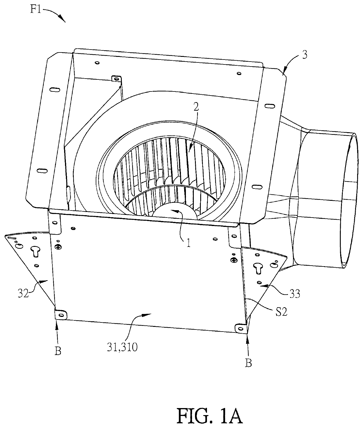
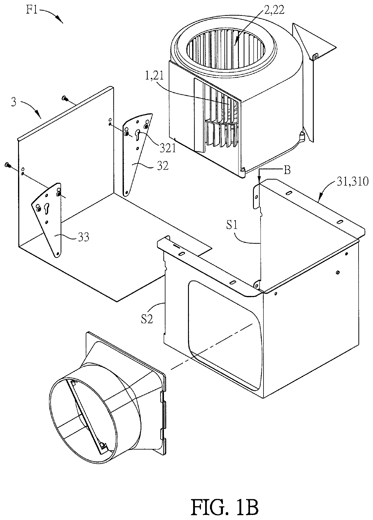
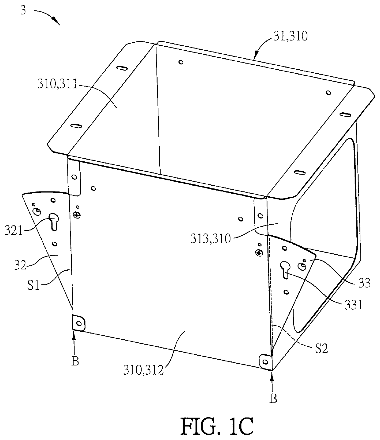
[0043]FIG. 1A is a perspective diagram of a ventilating fan according to an embodiment of the disclosure, FIG. 1B is an exploded view of the ventilating fan according to the embodiment of the disclosure, and FIG. 1C is a perspective diagram of a frame structure of FIG. 1A.

[0044]A ventilating fan F1 of the disclosure is configured to be mounted on an external structure. The ventilating fan F1 includes a driving device 1, a rotating blade assembly 2, and a frame structure 3. The driving device 1 drives the rotating blade assembly 2 to rotate. The rotating blade assembly 2 includes a hub 21 and at least a blade group 22. The blade group 22 is arranged on a periphery of the hub 21. The frame structure 3 is configured for mounting on the external structure. The driving device 1 and the ro...


PUM


Abstract

A ventilating fan includes a driving device, a rotating blade assembly, and a frame structure. The driving device drives the rotating blade assembly to rotate. The rotating blade assembly includes a hub and at least one blade group arranged on the periphery of the hub. The driving device and the rotating blade assembly are disposed in the frame structure. The frame structure includes a main body and a first mounting plate. The main body is formed by a plurality of side portions, and each side portion has at least one bending part for connecting to the adjacent side portion. At least one of the side portions has a first slot, which is disposed adjacent to the corresponding bend part. The first mounting plate is disposed corresponding to the first slot and located in the main body, and the first mounting plate has at least one fixing portion.

Description

BACKGROUND OF THE DISCLOSUREField of Disclosure[0001]The present disclosure relates to a ventilating fan and, in particular, to a ventilating fan having a movable mounting plate.Related Art[0002]The ventilating fan is mainly configured for enhancing the indoor air convention so as to maintain the fresh air.[0003]The conventional ventilating fan is fixed to the beams at the ceiling by additional fastening elements such as outer flanges or fixing plates of fan frame. However, the outer flanges or fixing plates of fan frame may not fit the original installation holes on the ceiling. Accordingly, it is necessary to modify or destroy the original installation holes on the ceiling for fixing the ventilating fan to the beams at the ceiling. Therefore, it is desired to optimize the installation of the ventilating fan without modifying or destroying the original installation holes of the ceiling.SUMMARY OF THE DISCLOSURE[0004]The present disclosure provides a ventilating fan to be mounted on...

Claims


Application Information

Patent Timeline
Patent Type & Authority Patents(United States)
IPC IPC(8): F04D29/62F04D29/42F04D25/08F04D29/60F04D29/28
CPCF04D29/601F04D25/08F04D29/4226F04D29/282F04D29/626
Inventor CHEN, CHUN-WEILIN, WEN-HSIANG
Owner DELTA ELECTRONICS INC
Why Eureka
Try Eureka