Ladar system and method with adaptive pulse duration

a ladar system and pulse duration technology, applied in the field of improved ladar systems and methods, can solve the problems of increasing interference sensitivity, intrinsic costlier than non-imaging receivers, and unsafe vehicles now about 150 feet closer

Active Publication Date: 2020-05-05
AEYE INC
View PDF223 Cites 26 Cited by
  • Summary
  • Abstract
  • Description
  • Claims
  • Application Information

AI Technical Summary

Problems solved by technology

This means that by the time the ladar system is able to declare the presence of the unsafe approaching vehicle, that unsafe vehicle is now about 150 feet closer.
However, the increased collection size (aperture) and collection time (dwell) results in increased sensitivity to interference (be it from retroreflectors and / or background light) relative to systems where the transmitter and receiver are coaxial.
Imaging receivers typically provide better mitigation of background clutter and other interference, but are intrinsically costlier than non-imaging receivers—largely due to multichannel receiver requirements (ROIC).

Method used


Image

  • Ladar system and method with adaptive pulse duration
  • Ladar system and method with adaptive pulse duration
  • Ladar system and method with adaptive pulse duration

Examples


Embodiment Construction

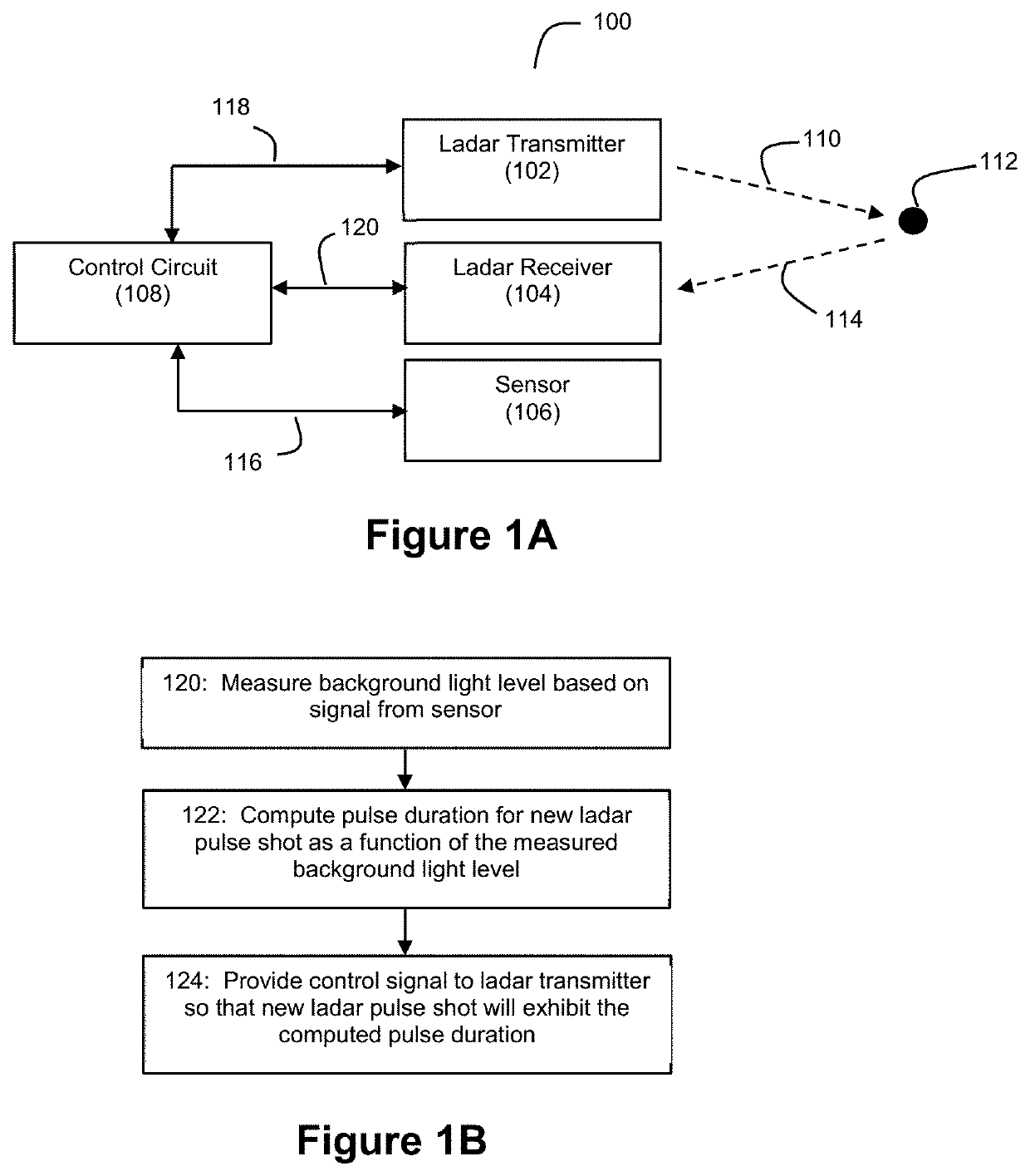
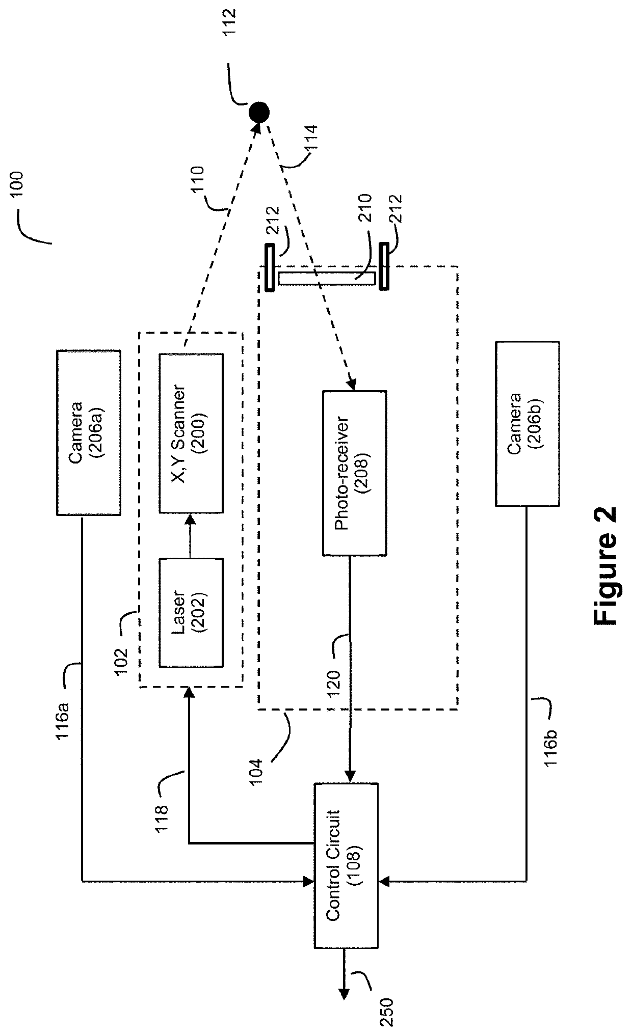
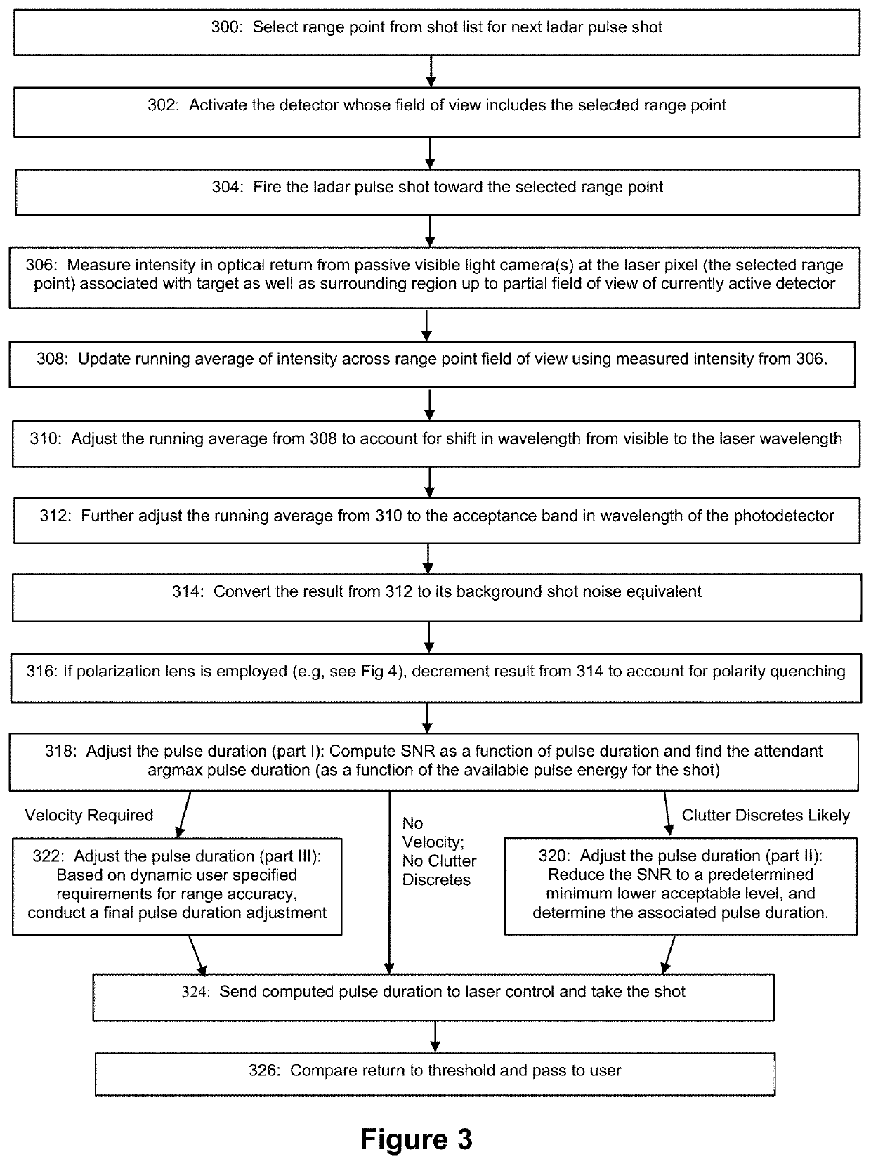
[0030]Discussed below are example embodiments of ladar systems that employ (1) adaptive pulse duration where the duration of the ladar pulses is adjusted as a function of measured background light (2) polarization diversity in the ladar receiver to improve detection capabilities, and (3) a cross-receiver to isolate interference. For ease of discussion, these features will be separately discussed with reference to example embodiments. However, it should be understood that a practitioner may choose to incorporate any or all of these technical innovations into the same ladar system if desired.

I. Adaptive Pulse Duration

[0031]FIG. 1A depicts an example ladar system 100 that can be used to adapt the duration of ladar pulses as a function of incident background light. The system 100 can employ a bistatic ladar transmitter 102 and ladar receiver 104. As an example, the ladar receiver 104 can be spatially offset from the ladar transmitter in a range between +30 to −30 degrees in the azimuth ...


PUM


Abstract

A ladar system and related method are disclosed where the ladar system includes a sensor that senses background light levels. A control circuit of the ladar system (1) measures the sensed background light levels and (2) controllably adjusts a pulse duration for a new ladar pulse based on the measured background light levels. A ladar transmitter can then transmit the new ladar pulse, wherein the new ladar pulse has the adjusted pulse duration. In an example embodiment, this technique for adaptive pulse duration can be employed in the ladar system where the ladar transmitter and ladar receiver are arranged in a bistatic architecture.

Description

CROSS-REFERENCE AND PRIORITY CLAIM TO RELATED PATENT APPLICATIONS[0001]This patent application claims priority to U.S. provisional patent application Ser. No. 62 / 837,767, filed Apr. 24, 2019, and entitled “Agile Bistatic Ladar System and Method”, the entire disclosure of which is incorporated herein by reference.[0002]This patent application is also related to (1) U.S. patent application Ser. No. 16 / 407,558, filed this same day, and entitled “Agile Bistatic Ladar System and Method”, (2) U.S. patent application Ser. No. 16 / 407,570, filed this same day, and entitled “Ladar System and Method with Frequency Domain Shuttering”, (3) U.S. patent application Ser. No. 16 / 407,589, filed this same day, and entitled “Ladar System and Method with Polarized Receivers”, (4) U.S. patent application Ser. No. 16 / 407,598, filed this same day, and entitled “Ladar System and Method with Multi-Dimensional Point Cloud Data Including Polarization-Specific Data”, (5) U.S. patent application Ser. No. 16 / 407,...

Claims


Application Information

Patent Timeline
Patent Type & Authority Patents(United States)
IPC IPC(8): G01S17/26G01S7/481G01S17/89
CPCG01S7/4811G01S17/26G01S17/89G01S17/003G01S17/86G01S17/931G01S7/497G01S7/484G01S7/487G01S17/42G01S17/10G01S7/499
Inventor DUSSAN, LUIS CARLOSSTEINHARDT, ALLANGREENE, JORDAN SPENCERWANG, ALLEN CHI-LUENVYAS, NITINREJALY, DARYOOSH
Owner AEYE INC
Why Eureka
Try Eureka