AI technical title is built by Patsnap AI team. It summarizes the technical point description of the patent document.
a power conversion device and power supply technology, applied in the direction of emergency power supply arrangement, process and machine control, instruments, etc., can solve problems such as overcurrent or overvoltage, and achieve the effect of preventing overcurrent or overvoltage and simple structur
Active Publication Date: 2020-05-05
TOSHIBA MITSUBISHI-ELECTRIC IND SYST CORP
View PDF13 Cites 1 Cited by
Summary
Abstract
Description
Claims
Application Information
AI Technical Summary
This helps you quickly interpret patents by identifying the three key elements:
Problems solved by technology
Method used
Benefits of technology
Benefits of technology
[0012]According to the present invention, it is possible for the power conversion device to prevent an overcurrent or an overvoltage from occurring with a simple structure.
Problems solved by technology
In the power conversion device described above, if one of a plurality of semiconductor switching elements is damaged and short-circuited, an overcurrent or an overvoltage may occur.
Method used
Image
Click on the blue label to locate the original text in one second.
Reading with bidirectional positioning of images and text.
Examples
Embodiment Construction
[0021]Hereinafter, embodiments of the present invention will be described in detail with reference to the drawings. In the following description, the same or corresponding portions in the drawings will be denoted by the same reference numerals, and the description thereof will not be repeated.
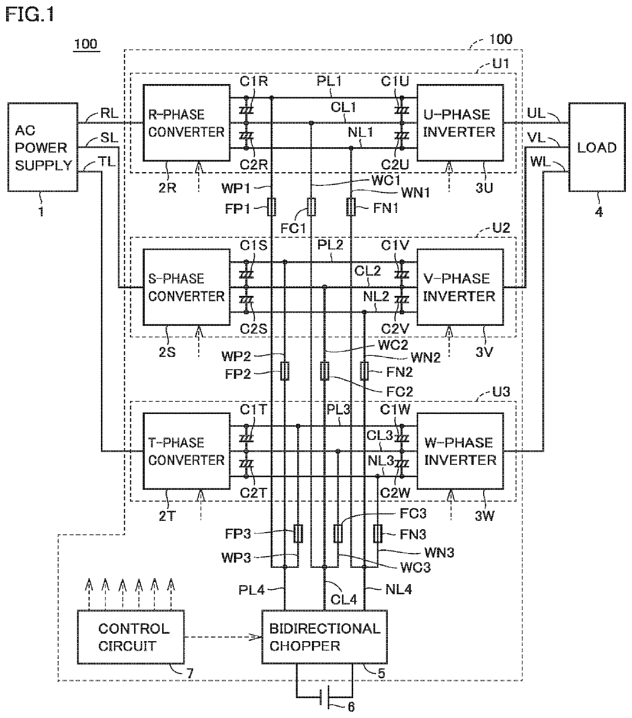
[0022]FIG. 1 is a schematic block diagram illustrating the configuration of a main circuit of a power conversion device 100 according to an embodiment of the present invention. The power conversion device 100 according to the present embodiment is used in, for example, an uninterruptible power supply apparatus. An AC power supply 1 is configured to supply a three-phase AC power of commercial frequency to the power conversion device 100. A load 4 is driven by the three-phase AC power of commercial frequency supplied from the power conversion device 100.
[0023]With reference to FIG. 1, the power conversion device 100 includes three converter units U1 to U3 connected in parallel between the AC powe...
PUM
Abstract
A first wire (WP1, WN1, WC1) is provided between a first converter unit (U1) and a DC bus line (PL4, NL4, CL4). A second wire (WP2, WN2, WC2) is provided between a second converter unit (U2) and a DC bus line (PL4, NL4, CL4). A third wire (WP3, WN3, WC3) is provided between a third converter unit (U3) and a DC bus line (PL4, NL4, CL4). A first fuse (FP1, FN1, FC1) is inserted in each of the first wire (WP1, WN1, WC1). A second fuse (FP2, FN2, FC2) is inserted in each of the second wire (WP2, WN2, WC2). A third fuse (FP3, FN3, FC3) is inserted in each of the third wire (WP3, WN3, WC3).
Description
TECHNICAL FIELD[0001]The present invention relates to a power conversion device.BACKGROUND ART[0002]Generally, a power conversion device used in an uninterruptible power supply apparatus or the like includes a converter configured to convert AC power from a commercial AC power supply into DC power and an inverter configured to convert DC power into AC power with a desired frequency and a desired voltage.[0003]For example, WO 2010 / 095241 (PTL 1) discloses an uninterruptible power supply apparatus constituted by a power conversion device including a three-level converter and a three-level inverter. In the power conversion device, each of the three-level converter and the three-level inverter includes a plurality of semiconductor switching elements.[0004]In the power conversion device described above, if one of a plurality of semiconductor switching elements is damaged and short-circuited, an overcurrent or an overvoltage may occur. In PTL 1, a fuse is connected between one terminal of...
Claims
Application Information
Patent Timeline
Application Date:The date an application was filed.
Publication Date:The date a patent or application was officially published.
First Publication Date:The earliest publication date of a patent with the same application number.
Issue Date:Publication date of the patent grant document.
PCT Entry Date:The Entry date of PCT National Phase.
Estimated Expiry Date:The statutory expiry date of a patent right according to the Patent Law, and it is the longest term of protection that the patent right can achieve without the termination of the patent right due to other reasons(Term extension factor has been taken into account ).
Invalid Date:Actual expiry date is based on effective date or publication date of legal transaction data of invalid patent.

