Pneumatic tire

a pneumatic tire and tread technology, applied in the field of pneumatic tires, can solve the problems of reduced rigidity of the tread portion, decreased drainage performance, and decreased steering stability on dry road surfaces, so as to improve steering stability, enhance wet performance, and ensure steering stability

Active Publication Date: 2020-05-12
THE YOKOHAMA RUBBER CO LTD
View PDF28 Cites 0 Cited by
  • Summary
  • Abstract
  • Description
  • Claims
  • Application Information

AI Technical Summary

Benefits of technology

[0005]The present technology provides a pneumatic tire including a tread pattern with an appropriate configuration that can achieve good steering stability on dry road surfaces and steering stability on wet road surfaces, which have a negative correlation, in a compatible manner and furthermore can provide improved uneven wear resistance.

Problems solved by technology

Unfortunately, if the number of the lug grooves in the tread portion is increased, the rigidity of the tread portion decreases and steering stability on dry road surfaces declines.
Conversely, if the number of the lug grooves in the tread portion is decreased, drainage performance decreases and steering stability on wet road surfaces declines.
In this way, steering stability on dry road surfaces and steering stability on wet road surfaces have a negative correlation with each other, and it is difficult to enhance both simultaneously.
If the tread portion is subdivided by the main grooves and the lug grooves, the tread portion is susceptible to uneven wear due to nonuniform rigidity.
Thus, it is more difficult to enhance uneven wear resistance as well as achieving good steering stability on dry road surfaces and steering stability on wet road surfaces in a compatible manner.

Method used


Image

  • Pneumatic tire
  • Pneumatic tire
  • Pneumatic tire

Examples


examples

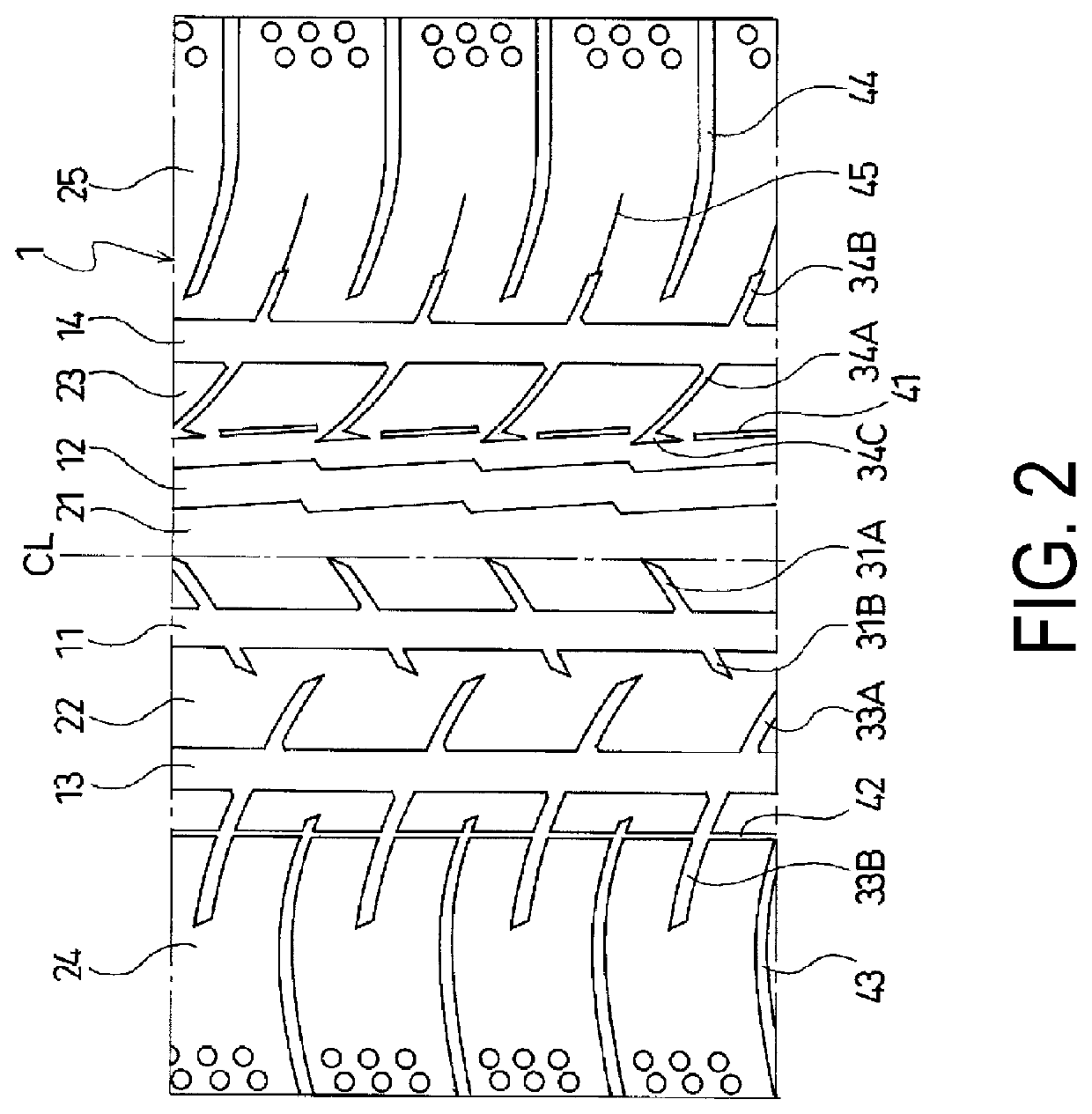
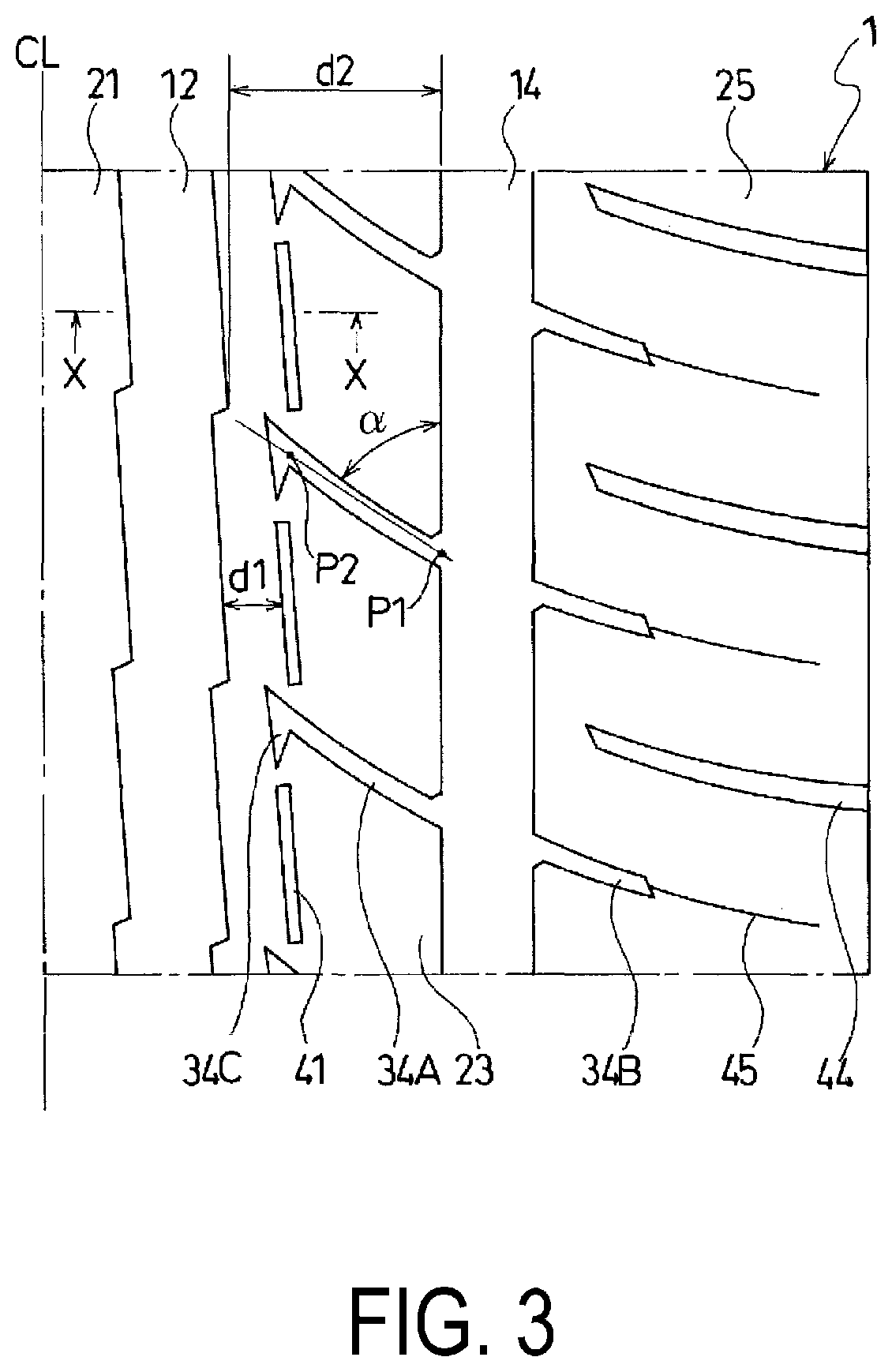
[0037]Tires of Examples 1 to 7 were manufactured with a tire size of 215 / 55R17. The pneumatic tires each included a tread portion, a pair of sidewall portions, and a pair of bead portions. As illustrated in FIG. 2, the pneumatic tire was provided, in the tread portion, with four main grooves including a pair of center main grooves extending in the tire circumferential direction and a pair of shoulder main grooves located outward of the center main grooves and extending in the tire circumferential direction; these main grooves defined five rows of land portions; one of the center main grooves had a zigzag shape in the tire circumferential direction, and the other main groove had a straight shape; a plurality of lug grooves extending inward from the shoulder main groove in the tire lateral direction and terminating without communicating with the center main groove were provided in the land portion located between the zigzag center main groove and the shoulder main groove; the lug groo...


PUM


Abstract

Provided is a pneumatic tire including a tread portion, sidewall portions, and bead portions. The tread portion comprises a center main groove extending in the tire circumferential direction and a shoulder main groove located outward of the center main groove and extending in the tire circumferential direction. A land portion is defined between the center main groove and the shoulder main groove. The center main groove has a zigzag shape in the tire circumferential direction. Lug grooves extending inward from the shoulder main groove in the tire lateral direction and terminating without communicating with the center main groove are provided in the land portion. A bent portion bent toward a first side in the tire circumferential direction is formed at a terminating end of each of the lug grooves. Narrow grooves extending discontinuously in the tire circumferential direction without communicating with the bent portions are formed in the land portion.

Description

TECHNICAL FIELD[0001]The present technology relates to a pneumatic tire including a tread portion including a center main groove extending in the tire circumferential direction, shoulder main grooves located outward of the center main groove and extending in the tire circumferential direction, and land portions extending in the tire circumferential direction defined between the center main groove and the shoulder main grooves; and particularly relates to a pneumatic tire including a tread pattern with an appropriate configuration that can achieve good steering stability on dry road surfaces and steering stability on wet road surfaces, which have a negative correlation, in a compatible manner and furthermore can provide improved uneven wear resistance.BACKGROUND ART[0002]Pneumatic tires have a tread pattern in which a plurality of rows of land portions are defined by a plurality of main grooves disposed in a tread portion and extend in the tire circumferential direction (for example,...

Claims


Application Information

Patent Timeline
Patent Type & Authority Patents(United States)
IPC IPC(8): B60C11/04B60C11/03B60C11/12B60C11/117
CPCB60C11/0304B60C11/0306B60C11/12B60C11/032B60C2011/0348B60C2011/0383B60C2011/1227B60C2011/0388B60C2011/1209B60C2011/0381B60C2011/0367B60C2011/0346B60C11/03
Inventor SHIBAI, TAKASHI
Owner THE YOKOHAMA RUBBER CO LTD
Why Eureka
Try Eureka