E-fuse cells

a technology of e-fuse cells and fuses, which is applied in the direction of semiconductor devices, semiconductor/solid-state device details, diodes, etc., can solve the problems of electrical fuses being prone to false programming and electrical fuses being accidentally programmed

Active Publication Date: 2020-05-12
GLOBALFOUNDRIES SINGAPORE PTE LTD
View PDF11 Cites 0 Cited by
  • Summary
  • Abstract
  • Description
  • Claims
  • Application Information

AI Technical Summary

Benefits of technology

[0006]In another exemplary embodiment, an e-fuse cell includes an e-fuse having a first end coupled to a source node and a second end selectively coupled to a ground. The exemplary e-fuse cell further includes a diode connected to the source node and the ground in parallel to the e-fuse to inhibit negative current flow across the e-fuse.

Problems solved by technology

However, e-fuses are susceptible to false programming due to electric overstress.
Because the physical structure of an e-fuse is very small and fragile, a typical resistance may be about 100 ohms, and devices with such small resistance are sensitive to electrical static discharge and floating supply voltage that can reside inside an integrated circuit.
Both electrical static discharge and floating supply voltage can potentially cause these electrical fuses to accidentally program themselves while in the manufacturing stage, system qualification phase, or during physical contact.

Method used


Image

  • E-fuse cells
  • E-fuse cells

Examples


Embodiment Construction

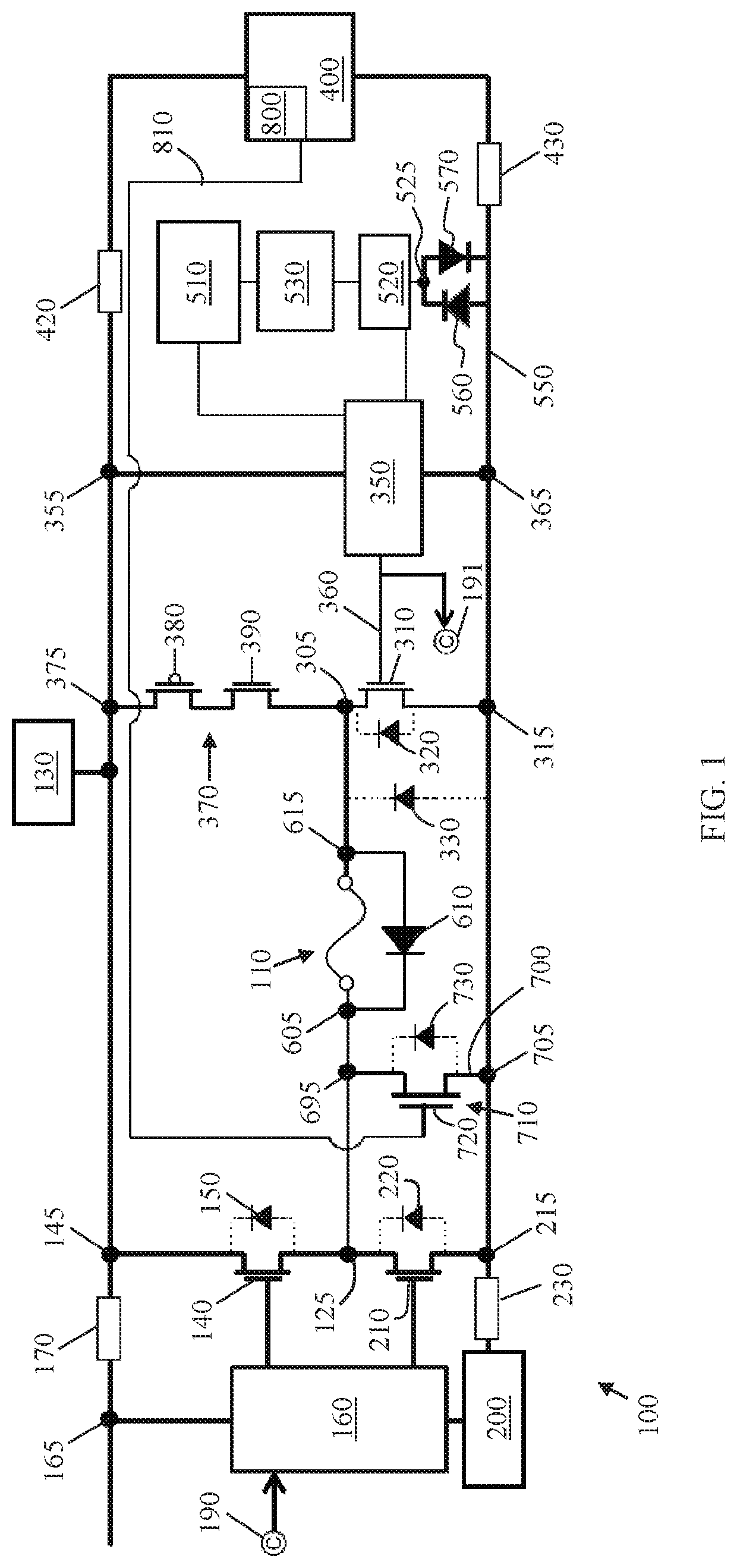
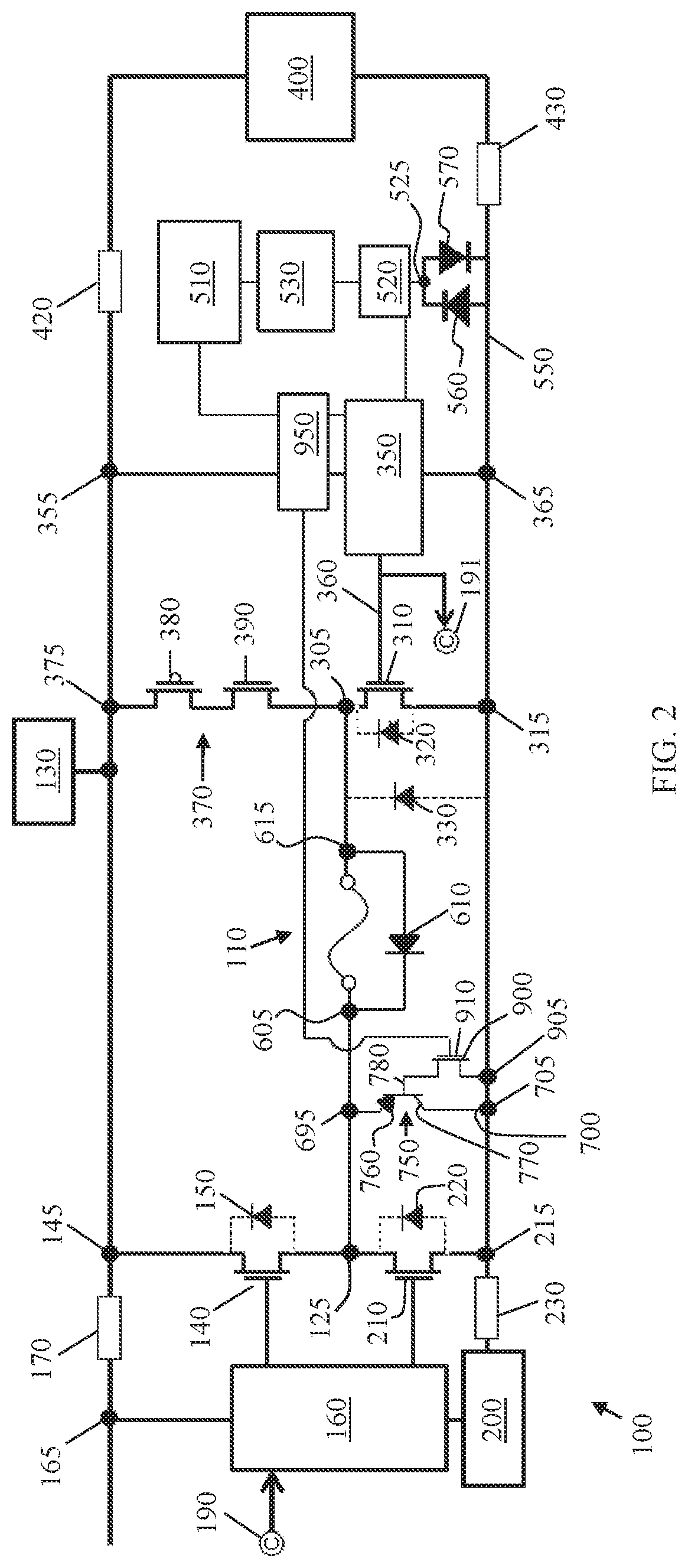
[0011]The following detailed description is merely exemplary in nature and is not intended to limit the e-fuse cells or methods for protecting e-fuses. Furthermore, there is no intention to be bound by any expressed or implied theory presented in the preceding technical field, background or brief summary, or in the following detailed description.

[0012]For the sake of brevity, conventional techniques related to conventional integrated circuit device fabrication and layout may not be described in detail herein. Moreover, the various tasks and processes described herein may be incorporated into a more comprehensive procedure or process having additional functionality not described in detail herein. Many conventional integrated circuit elements will only be mentioned briefly herein or will be omitted entirely without providing the well-known element details. Further, it is noted that integrated circuits include a varying number of components and that single components shown in the illus...


PUM


Abstract

E-fuse cells and methods for protecting e-fuses are provided. An exemplary e-fuse cell includes an e-fuse having a first end coupled to a source node and a second end selectively coupled to a ground. Further, the exemplary e-fuse includes a selectively activated shunt path from the source node to the ground. Also, the exemplary e-fuse includes a device for activating the shunt path in response to an electrical overstress event.

Description

TECHNICAL FIELD[0001]The technical field generally relates to semiconductor devices to semiconductor electrical fuse devices, i.e., e-fuses, and more particularly to the protection of e-fuses from accidental programming and electrical overstress (EOS) such as electric static discharge (ESD).BACKGROUND[0002]E-fuses may be utilized to repair integrated circuits after fabrication. E-fuses are generally preferred to laser fuses because e-fuses can be placed anywhere under the metal structure of a chip, thus potentially allowing for thousands of e-fuses to be used in a single chip. E-fuses are typically designed to break when a large electrical current passes through the e-fuses. By “blowing” these e-fuses during testing, technicians can monitor and adjust their functions to improve their quality, performance and power consumption without much human intervention.[0003]However, e-fuses are susceptible to false programming due to electric overstress. Because the physical structure of an e-...

Claims


Application Information

Patent Timeline
Patent Type & Authority Patents(United States)
IPC IPC(8): H01L27/02H01L23/525H01L27/06
CPCH01L27/0647H01L23/5256H01L27/0259H01L27/0266
Inventor LINEWIH, HANDOKOLEE, CHIEN-HSIN
Owner GLOBALFOUNDRIES SINGAPORE PTE LTD
Why Eureka
Try Eureka