Intermediate transfer member and image forming apparatus

Active Publication Date: 2020-05-19
KONICA MINOLTA INC
5 Cites 1 Cited by

AI-Extracted Technical Summary

Problems solved by technology

Particularly, with paper having grooves formed therein, such as non-smooth paper, there is a problem that sufficiently high image quality cannot be achieved with the above described conve...

Method used

[0022]According to the above equation, the permittivity ε1 of the intermediate transfer belt is increased, and the thickness d1 is reduced, so that the electric field strength E acting on the toner can be increased without any increase in the transfer voltage V, and the transfer efficiency can be improved while discharge is suppressed. However, if the rate of content of the ferroelectric material is raised to increase the permittivity of the intermediate transfer belt, the durability of the intermediate transfer belt drops, as described above. Further, if the intermediate transfer belt is made thicker to increase its durability, the electric field E becomes smaller, and the necessary voltage becomes higher. Therefore, the transfer efficiency does not become higher. In other words, it is difficult to achieve both improvement of the permittivity and improvement of the durability of an intermediate transfer belt.
[0023]In view of this, the inventor of the present invention pay attention to the conductive material to be added for providing an intermediate transfer member (hereinafter referred to as an intermediate transfer belt) with conductivity, and has developed a method of increasing the permittivity not by increasing the rate of content of a ferroelectric material but by using the conductive material. By this method, the rate of content of the ferroelectric material can be minimized, and both improvement of the permittivity and improvement of the durability can be achieved. As a result of repeated experiments using various conductive materials, it was found that carbon nanotubes are the most suitable as the conductive material that can achieve a sufficiently high permittivity even when the rate of content of the ferroelectric material is lowered.
[0025]As shown in FIG. 2A, in a combination of ferroelectric fillers and carbon black, the ferroelectric fillers do not bind to one another. To obtain a desired permittivity, it is necessary to add a large number of ferroelectric fillers, but doing so will lower the durability. On the other hand, in a combination of ferroelectric fillers and carbon nanotubes as shown in FIG. 2B, the carbon nanotubes bind the ferroelectric fillers to one another (that is, the carbon nanotubes contribute to improvement of the permittivity). Accordingly, a desired permittivity can be obtained without addition of a large number of ferroelectric fillers, and both improvement of the permittivity and improvement of the durability can be achieved. Particularly, in a case where the carbon nanotubes are oriented in the front-back direction of the intermediate transfer belt as shown in FIG. 2C, the ferroelectric fillers can be efficiently bound to one another. Accordingly, the rate of content of the ferroelectric fillers can be further lowered, and it is possible to achieve both further improvement of the permittivity and further improvement of the durability. In other words, as the carbon nanotubes bind the ferroelectric fillers to one another, the polarizing action of the ferroelectric fillers can be increased (to the same state as in a case where the rate of content of the ferroelectric fillers is increased), and thus, the permittivity can be improved. As a result, the rate of content of the ferroelectric fillers for obtaining a desired permittivity can be lowered, and the durability can be improved.
[0029]The conductive fillers contained in the intermediate transfer belt according to an embodiment of the present invention are CNTs, and the diameter of the CNTs is preferably not smaller than 30 nm and not greater than 150 nm, and the length of the CNTs is preferably not smaller than 5 μm and not greater than 12 μm. As the diameter and the length of the CNTs are set within the above respective ranges, it is possible to provide the intermediate transfer belt with appropriate conductivity, and efficiently bind the ferroelectric fillers to one another.
[0030]A functional group may be covalently bound to the CNTs as necessary. For example, CNTs are treated with strong acid, to generate oxidized CNTs having carboxylic acid introduced into the surfaces. After being made to react with thionyl chloride, the oxidized CNTs are made to react with alkyl alcohol or the like, so that chemically decorated CNTs that dissolve in an organic solvent can be generated. Using such chemically decorated CNTs, it is possible to disperse CNTs uniformly in the resin material. Further, with the CNTs being dispersed in the resin material, an electric field from the outside is applied thereto. Thus, the CNTs can be oriented in a desired direction, and the permittivity of the intermediate transfer belt can be improved.
[0031]Meanwhile, the ferroelectric fillers contained in the intermediate transfer belt according to an embodiment of the present invention preferably include barium titanate, strontium titanate, and/or calcium titanate. As these ferroelectric fillers are combined w...

Benefits of technology

[0008]The present invention has been made in view of the above problems, and a principal objective thereof is to...

Abstract

An intermediate transfer member that is used for electrophotographic image formation, includes carbon nanotubes and ferroelectric fillers in a base material layer containing a resin material as a principal component.

Application Domain

Material nanotechnologyElectrographic process apparatus

Technology Topic

Carbon nanotubePolymer chemistry +3

Image

  • Intermediate transfer member and image forming apparatus
  • Intermediate transfer member and image forming apparatus
  • Intermediate transfer member and image forming apparatus

Examples

  • Experimental program(3)

Example

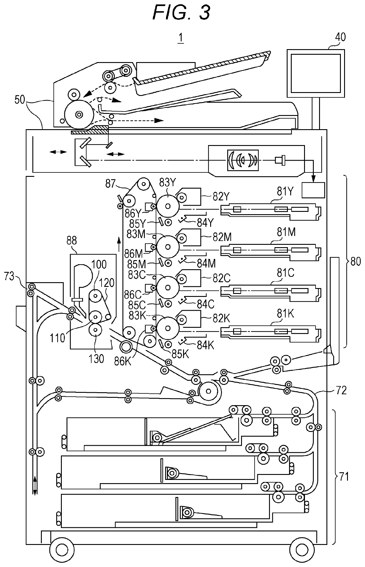
[0055]Specifically, in Examples 1 to 4, 6, and 7, CNTs were used as the conductive fillers, barium titanate was used as the ferroelectric fillers, and the rate of content of the ferroelectric fillers, the total rate of content of the CNTs and the ferroelectric fillers, the diameter of the CNTs, the length of the CNTs, and the film thickness were varied in the preparation of intermediate transfer belts. In the preparation of an intermediate transfer belt in Example 5, strontium titanate was used as the ferroelectric fillers, and the other conditions were the same as in Example 1.
[0056]In Comparative Examples 1 and 3, carbon black (CB) was used as the conductive fillers, barium titanate was used as the ferroelectric fillers, and the rate of content of the ferroelectric fillers, and the total rate of content of the CB and the ferroelectric fillers were varied in the preparation of intermediate transfer belts. In Comparative Example 2, CNTs were used as the conductive fillers, and titanium oxide was added, to prepare an intermediate transfer belt. In Comparative Example 4, CNTs were used as the conductive fillers, and no ferroelectric fillers were added, to prepare an intermediate transfer belt.
[0057]The intermediate transfer belts prepared under the conditions in Examples 1 to 7 and Comparative Examples 1 to 4 were subjected to permittivity measurement, measurement of tensile elongation at break, image evaluation, and durability evaluation. In the description below, specific methods for the respective evaluations are explained.
[0058]
[0059]As shown in FIG. 5, thin-film electrodes with a resistance of one-digit Ω were formed on the surface of the intermediate transfer belt 87a by sputtering or the like, and were cut out with a mold of 10 mm φ, so that measurement samples were prepared. An impedance analyzer (manufactured by Solartron Analytical; Model 12608W) was used, to measure relative permittivities by an electrode contact method from 1 Hz to 1 MHz in an AC impedance measurement mode.
[0060]
[0061]On the basis of ISO527 and RS K7161, the intermediate transfer belts were processed to create dumbbell-shaped test pieces, and each test piece was pulled from both sides by an extensometer capable of measuring changes in the distance between marked lines with ISO9513 Class 1 accuracy. The elongation rate at the time when the intermediate transfer belt broke (the ratio of the extended length to the original length) was then measured.
[0062]
[0063]Leather-like 203 g paper was used as uneven paper, and a predetermined image was formed on this leather-like 203 g paper with an image forming apparatus “bizhub PRESS C1100” (Konica Minolta). Toner transfer states at concave portions were then rated on a scale of one to five. Note that the evaluation environments were 20° C. in temperature and 50% in humidity, and the target level is rank 4 or higher.
[0064]Rank 5: Completely transferred.
[0065]Rank 4: Several points are missing at two-layer portions. There is no problem with the single-color portions.
[0066]Rank 3: Some two-layer portions are missing at random. There is no problem with the single-color portions.
[0067]Rank 2: Some single-color portions are missing at random.
[0068]Rank 1: The single-color portions are completely missing.
[0069]
[0070]With the image forming apparatus “bizhub PRESS C1100” (Konica Minolta), the damages states of the intermediate transfer belt when 1000K sheets were fed and when 2000K sheets were fed were compared in the following four levels. Note that the evaluation environments were 20° C. in temperature and 50% in humidity, and the target level is “∘” or higher without any cracks.
[0071]⊚: No cracks after 2000K feed.
[0072]∘: No cracks after 1000K feed.
[0073]Δ: Damage was observed at the edges after 1000K feed.
[0074]x: Damage was observed at the center portion as well as at the edges after 1000K feed.
[0075]FIGS. 6A and 6B are tables that summarize the conditions for preparation of the intermediate transfer belts of Examples 1 to 7 and Comparative Examples 1 to 4, and the results of evaluation regarding the above mentioned evaluation items. The tables are divided for convenience in plotting.
[0076]Examples 1 to 4, 6, and 7 in FIG. 6A are examples in which barium titanate was used as the ferroelectric fillers, and CNTs were used as the conductive fillers. The transferability rank in the image evaluation is 4 or higher, which is the target level, and the durability is evaluated as “∘” or higher, which is also the target level. Accordingly, Examples 1 to 4, 6, and 7 are preferable as the conditions for preparation of an intermediate transfer belt. Specifically, it is apparent that the rate of content of the ferroelectric fillers in the resin material is preferably 10% to 30% by volume, the total rate of content of the ferroelectric fillers and the CNTs is preferably 12% to 32% by volume (the preferred range of the rate of content of the CNTs is 2% to 4% by volume), the CNT diameter is preferably 30 to 150 nm, the CNT length is preferably 5 to 12 μm, and the film thickness is preferably 50 to 100 μm. It is also apparent that the relative permittivity of the intermediate transfer belt is preferably 30 to 60 (particularly 40 to 50, which corresponds to rank 5 in transferability), and the tensile elongation at break is preferably 20% to 100%.
[0077]Further, as can be seen from the result of comparison between Example 1 and Example 5, in a case where strontium titanate was used as the ferroelectric filler seed, the transferability rank is 5, and the durability is“⊚”. This shows that barium titanate or strontium titanate is preferable as the ferroelectric fillers. Although not shown in the table, the same results as above were obtained when calcium titanate was used as the ferroelectric fillers, and the other conditions were the same as in Example 1 in preparing an intermediate transfer belt. Accordingly, calcium titanate is also preferable as the ferroelectric fillers.

Example

[0078]Further, as shown in Comparative Example 1 in FIG. 6B, in a case where carbon black is used as the conductive filler seed, the rate of content of the ferroelectric fillers needs to be increased to make the relative permittivity fall within the above range of 30 to 60. As the rate of content of the ferroelectric fillers increases (to 50% by volume in this example), the tensile elongation at break decreases (to 2% in this example), resulting in poorer durability. Further, as shown in Comparative Example 3, when the rate of content of the ferroelectric fillers is reduced (to 30% by volume in this example) to increase the tensile elongation at break, the relative permittivity decreases (to 15% in this example) and moves out of the range of 30 to 60 shown in Examples 1 to 7, resulting in a lower rank in transferability (dropping to rank 2 in this example). This proves that it is important to use CNTs as the conductive fillers.

Example

[0079]Furthermore, as shown in Comparative Examples 2 and 4 in FIG. 6B, even in a case where CNTs are used as the conductive filler seed, if any ferroelectric fillers are not added, the relative permittivity decreases (to 20 in Comparative Example 2, and to 10 in Comparative Example 4), and moves out of the range of 30 to 60 shown in Examples 1 to 7. Therefore, the rank in transferability drops (to rank 3 in Comparative Example 2, and to rank 1 in Comparative Example 4). This shows that it is important to combine CNTs and ferroelectric fillers.
[0080]In accordance with the above results, CNTs are used as the conductive fillers, barium titanate, strontium titanate, and/or calcium titanate is used as the ferroelectric fillers, the CNTs are combined with these ferroelectric fillers, the rate of content of the ferroelectric fillers is 10% to 30% by volume, the total rate of content of the ferroelectric fillers and the CNTs is 12% to 32% by volume (the preferred range of the rate of content of the CNTs is 2% to 4% by volume), the CNT diameter is 30 to 150 nm, the CNT length is 5 to 12 μm, and the film thickness is 50 to 100 μm. The relative permittivity of an intermediate transfer belt prepared under such conditions is 30 to 60 (preferably 40 to 50), the tensile elongation at break is 20% to 100%, and the more preferable results of image evaluation and durability evaluation can be achieved.
[0081]The present invention is not limited to the above examples, and any appropriate modifications can be made to the configurations and the control thereof, without departing from the scope of the present invention.
[0082]For example, in the above embodiments and Examples, an endless intermediate transfer belt is used as an example of an intermediate transfer member. However, the present invention can also be applied to an intermediate transfer member of any appropriate mode in which a toner image formed on an image carrier such as a photosensitive drum is temporarily transferred (primary transfer) before being transferred onto an image support member such as a paper medium (secondary transfer).
[0083]Further, in the above embodiments and Examples, barium titanate, strontium titanate, and calcium titanate have been mentioned as examples of ferroelectric fillers. However, these materials may be used in combination with one another, or some other material that can be combined with CNTs to achieve a desired permittivity even if the rate of content thereof is low may be used.
[0084]In the above embodiments and Examples, CNTs are used as an example of the conductive fillers. However, it is also possible to use some other material that can provide conductivity, and bind the ferroelectric fillers to one another to increase the permittivity, like CNTs.
[0085]The present invention can be applied to an intermediate transfer member to be used for electrophotographic image formation, and an image forming apparatus including the intermediate transfer member.
[0086]With an intermediate transfer member and an image forming apparatus according to an embodiment of the present invention, high image quality can be achieved.
[0087]This is because the base material layer of the intermediate transfer member containing a resin material as its principal component contains carbon nanotubes and ferroelectric fillers (such as barium titanate, strontium titanate, or calcium titanate).
[0088]Although embodiments of the present invention have been described and illustrated in detail, the disclosed embodiments are made for purposes of illustration and example only and not limitation. The scope of the present invention should be interpreted by terms of the appended claims

PUM

no PUM

Description & Claims & Application Information

We can also present the details of the Description, Claims and Application information to help users get a comprehensive understanding of the technical details of the patent, such as background art, summary of invention, brief description of drawings, description of embodiments, and other original content. On the other hand, users can also determine the specific scope of protection of the technology through the list of claims; as well as understand the changes in the life cycle of the technology with the presentation of the patent timeline. Login to view more.

Similar technology patents

Photothermographic material

InactiveUS20060057512A1high image qualityexcellent image storability
Owner:FUJIFILM CORP +1

Camera lens group

PendingCN109031626Ahigh image qualityImprove light transmittance
Owner:ZHEJIANG SUNNY OPTICAL CO LTD

Classification and recommendation of technical efficacy words

Why Eureka
Try Eureka