Use of ancillary devices/accessories in radiotherapy systems

a technology of ancillary devices and radiotherapy systems, applied in the field of radiotherapy, can solve the problems of non-biological objects, affecting the efficacy of beam therapy for patients, and not being taken into accoun

Active Publication Date: 2020-06-02
ELEKTA AB
View PDF12 Cites 6 Cited by
  • Summary
  • Abstract
  • Description
  • Claims
  • Application Information

AI Technical Summary

Problems solved by technology

If these accessories are located in the path of the radiotherapeutic beam, they may affect the efficacy with which the beam provides the therapy to the patient.
However, non-biological objects such as the devices / accessories will not usually be clearly visible to an MR scanner, and thus cannot be taken into account in an automated treatment planning process; accordingly an operator has to carefully locate and orientate such devices prior to treatment, and manually input information of their location, orientation and composition into the TPS in order for the radiotherapy to be applied in accordance with the predetermined treatment plan.
This is time-consuming, and does not account for any movement which may occur during a radiotherapy treatment.

Method used


Image

  • Use of ancillary devices/accessories in radiotherapy systems
  • Use of ancillary devices/accessories in radiotherapy systems
  • Use of ancillary devices/accessories in radiotherapy systems

Examples


Embodiment Construction

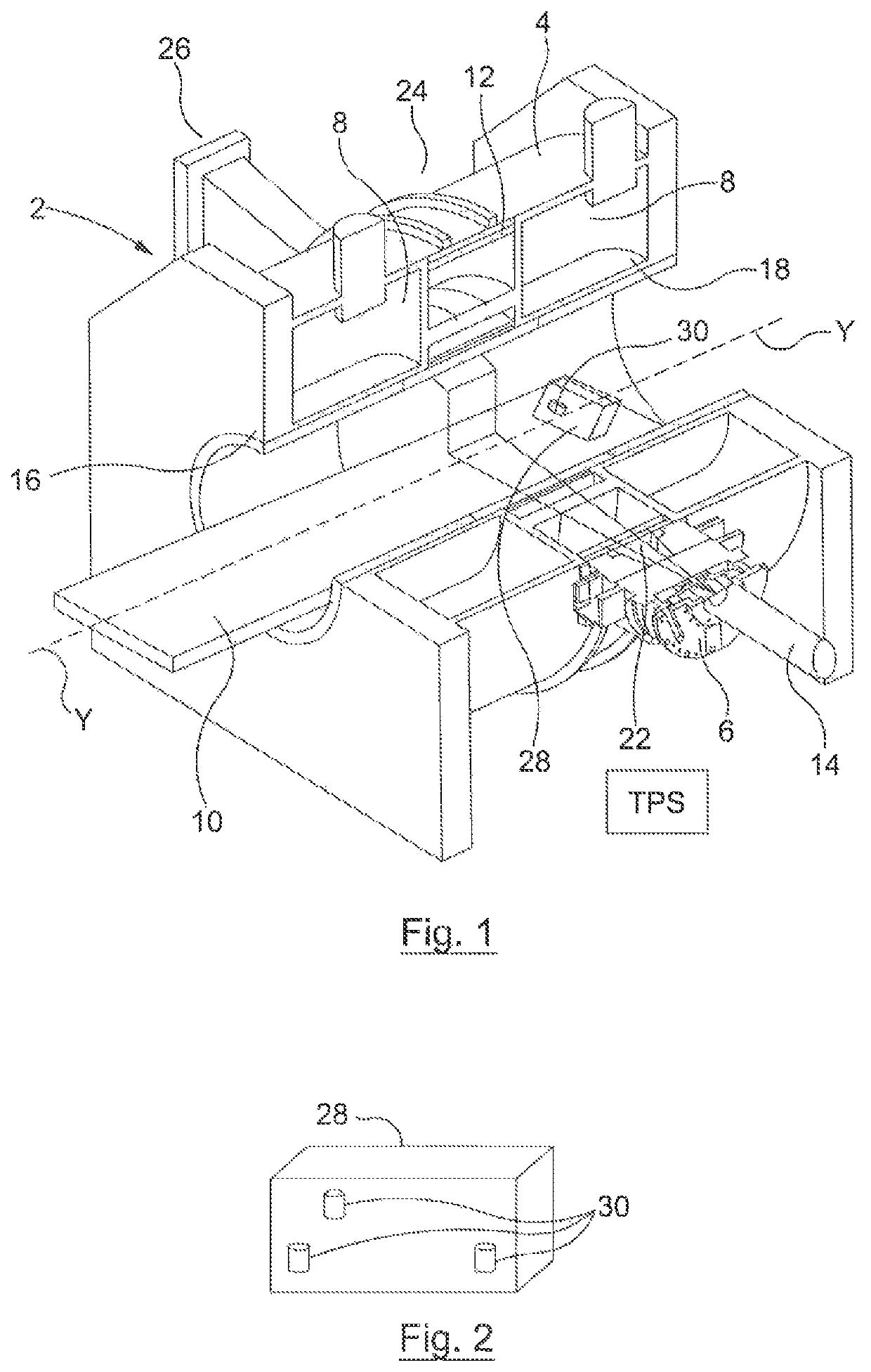
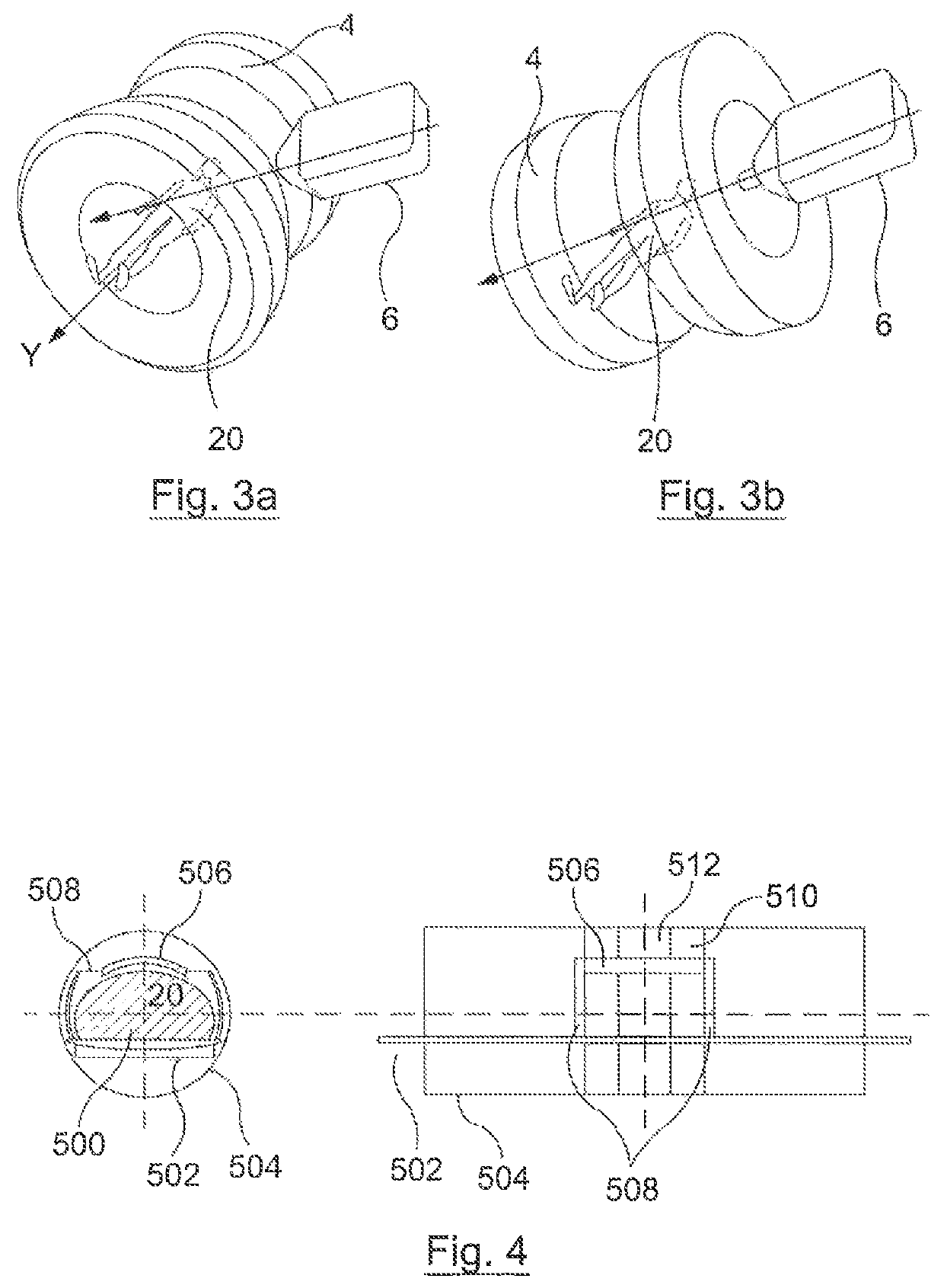
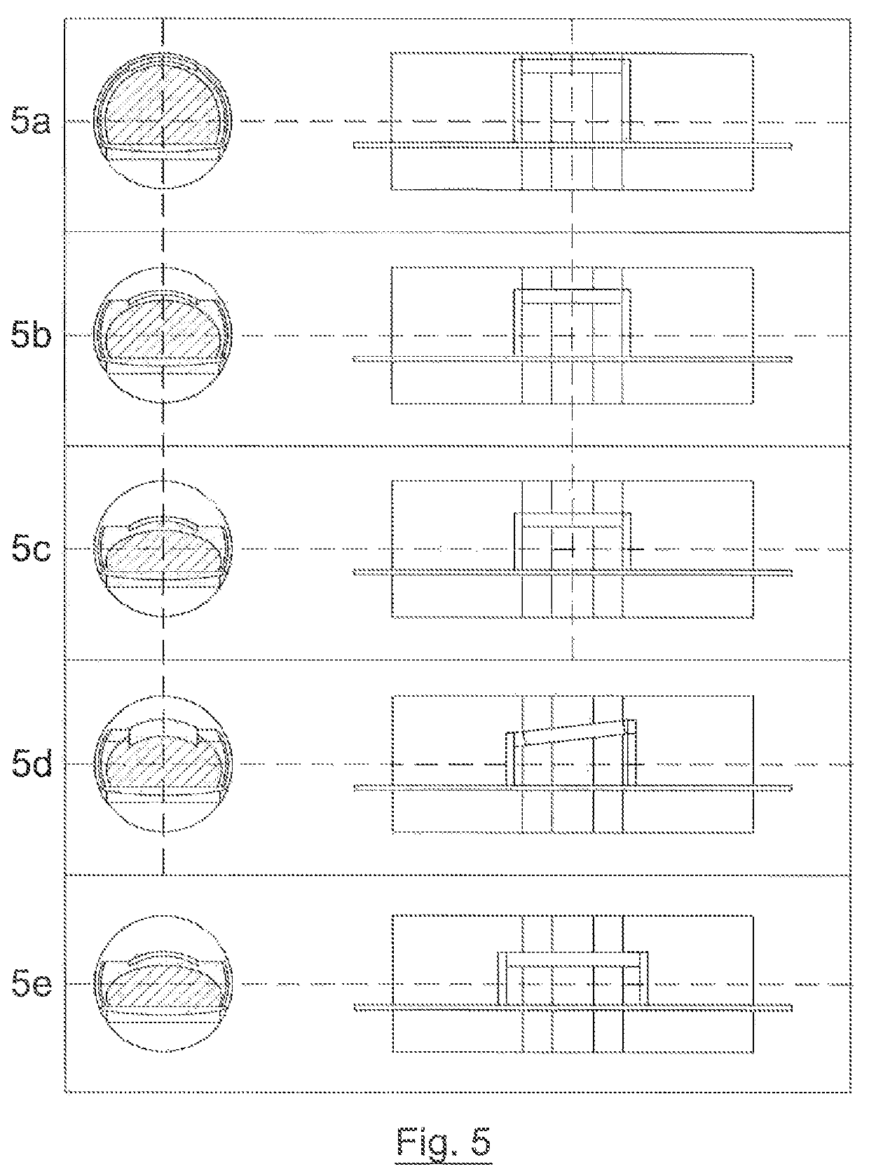
[0017]FIG. 1 shows a system 2 comprising a radiotherapy apparatus 6 and a magnetic resonance imaging (MRI) apparatus 4. The system includes a couch 10, for supporting a patient in the apparatus. The couch 10 is movable along a horizontal, translation axis (labelled “Y”), such that a patient resting on the couch is moved into the radiotherapy and MRI apparatus. In one embodiment, the couch 10 is rotatable around a central vertical axis of rotation, transverse to the translation axis, although this is not illustrated. The couch 10 may form a cantilever section that projects away from a support structure (not illustrated). In one embodiment, the couch 10 is moved along the translation axis relative to the support structure in order to form the cantilever section, i.e. the cantilever section increases in length as the couch is moved and the lift remains stationary. In another embodiment, both the support structure and the couch 10 move along the translation axis, such that the cantileve...


PUM


Abstract

A system or use with a radiotherapy system includes a scanner for producing images of at least one object within an imaging volume, a radiotherapy apparatus including a source of therapeutic radiation adapted to deliver a beam of radiation into the at least one object, a treatment planning system for controlling the source so as to deliver radiation in accordance with a predetermined plan for treating a patient and with the images of the at least one object, and at least one device within and / or adjacent to the imaging volume. The at least one device comprises at least one first marker which is visible to the scanner and at least one MR second marker which is visible to an MR scanner. The system further comprises a database containing data including the markers associated with the at least one device and at least its geometric and density characteristics.

Description

CROSS REFERENCE TO RELATED APPLICATION[0001]The present application claims the benefits of priority to GB 1318805.7, filed on Oct. 24, 2013, and GB 1413104.9, filed Jul. 24, 2014. The entire content of each of these applications is incorporated herein by reference.FIELD OF THE INVENTION[0002]The present invention relates to radiotherapy, particularly but not exclusively Magnetic Resonance (MR) guided radiotherapy.BACKGROUND ART[0003]Incorporating real-time image guidance into radiotherapy can improve tumour targeting accuracy, enabling better avoidance of critical structures and reducing side effects. Such guidance is of particular benefit if a non-ionizing imaging technique such as MRI (magnetic resonance imaging) is employed. Work is currently being undertaken to integrate a linear accelerator with an MR scanner. By integrating high-quality MRI with a source of therapeutic radiation, such as a linear accelerator, tissue can be tracked online and therapeutic radiation beams can be ...

Claims


Application Information

Patent Timeline
Patent Type & Authority Patents(United States)
IPC IPC(8): A61N5/10
CPCA61N5/1065A61N5/1049A61N5/1047A61N5/1064A61N5/1067A61N2005/1051A61N2005/1055
Inventor KNOX, CHRISTOPHER CHARLESWINCHESTER, NEILROBERTS, DAVID ANTHONYSTIEF, JILL
Owner ELEKTA AB
Why Eureka
Try Eureka