Combined MRI and radiation therapy system

a radiation therapy system and mri technology, applied in the field of combined mri and radiation therapy equipment, can solve the problems of inability to intensity modulation, inability to detect stray fields, and inability to achieve significant amounts of dense material screening, etc., to achieve the effect of reducing the diameter of the main magnet coil and reducing the magnitude of a stray field

Active Publication Date: 2016-12-27
SIEMENS HEALTHCARE GMBH
View PDF18 Cites 31 Cited by
  • Summary
  • Abstract
  • Description
  • Claims
  • Application Information

AI Technical Summary

Benefits of technology

[0029]According to the present invention, the LINAC required for generating an electron beam, which is in turn required for generating a radiation beam, is located radially outside of the main magnet, and accordingly allows the diameter of the main magnet coils to be reduced.
[0030]The invention is applicable to actively-shielded solenoidal magnets, wherein shield coils of diameter greater than the main coils, but arranged coaxially with the main magnet coils, carry a current in the opposite direction as compared to a current carries by the main magnet coils. As is well known to those skilled in the art, such shield coils reduce the magnitude of a stray field around the MRI system. Preferably, the LINAC is arranged parallel to the axis of the main magnet, radially positioned between the radially outer surface of the main magnet coils and the radially inner surface of the shield coils. In this way, the combined MRI and radiation therapy equipment of the present invention has an outer diameter similar to that of a comparable MRI system, allowing installation in locations which would be impractical for a conventional combined MRI and radiation therapy system.

Problems solved by technology

Certain examples of combined MRI and radiation therapy equipment are known, but suffer from certain drawbacks.
The use of a cobalt-60 source involves difficulties in storage, and prevention of over-exposure by operators.
Screening of such sources can only be achieved by significant amounts of dense material such as lead or tungsten.
The radiation produced is however of relatively low energy, and cannot be intensity-modulated.
The accelerators required to produce an electron beam, typically linear accelerators, are very sensitive to transverse magnetic fields, which makes their incorporation into MRI equipment difficult.
The magnetic field deflects the path of the electron beam within the accelerators, destroying the efficacy of such radiation sources.
The radially-aligned LINAC is arranged on the mid-plane of the magnet, and requires a lot of space around the magnet, making it impractical for many installations.
This known arrangement, however, suffers from certain disadvantages.
This is difficult to achieve when the LINAC is positioned close to the main magnet coils, as the electron beam quality may be degraded by variations in the magnetic field experienced by the electron beam due to variations in magnetic field orientation and strength.

Method used


Image

  • Combined MRI and radiation therapy system
  • Combined MRI and radiation therapy system
  • Combined MRI and radiation therapy system

Examples


Embodiment Construction

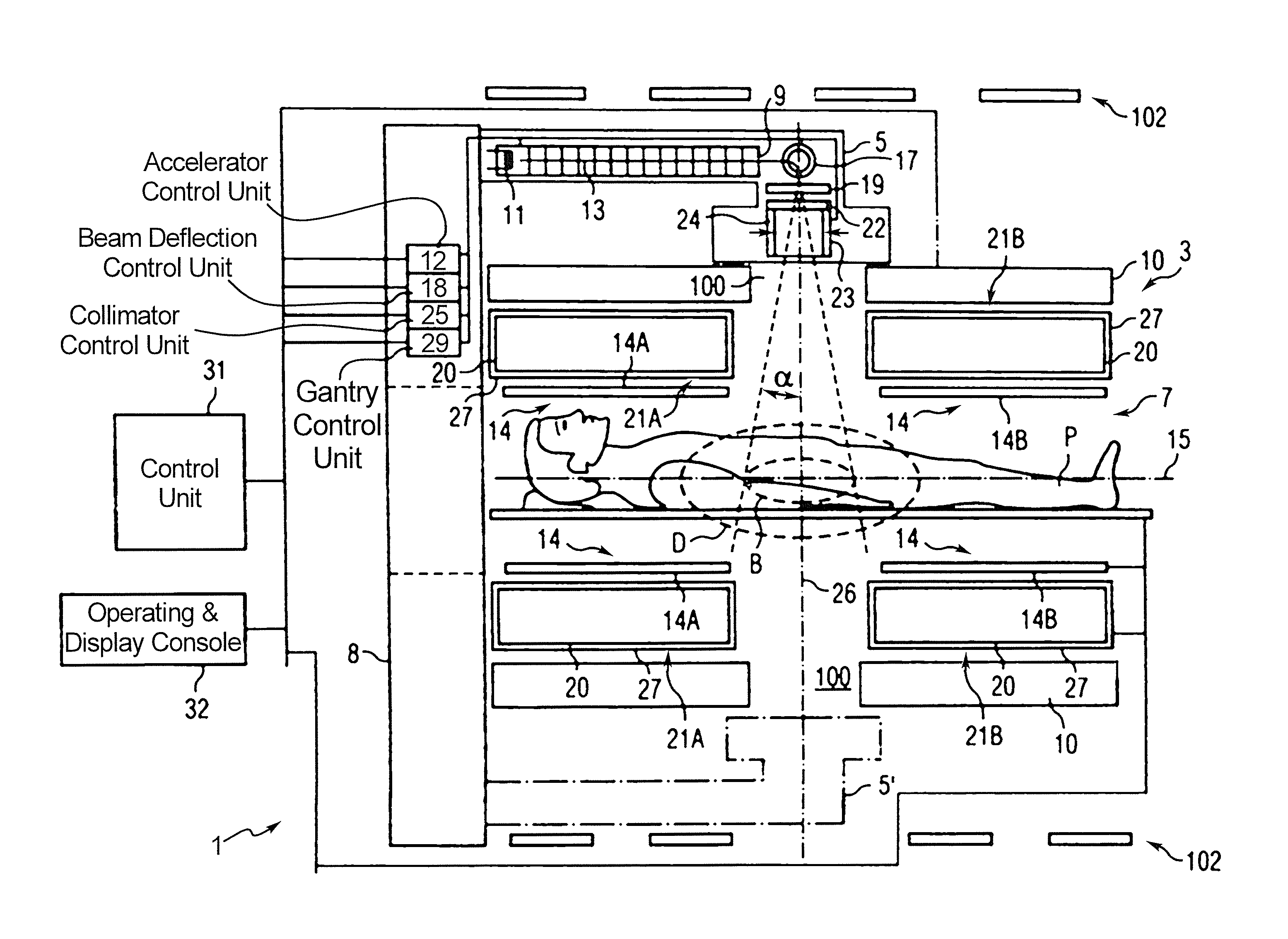
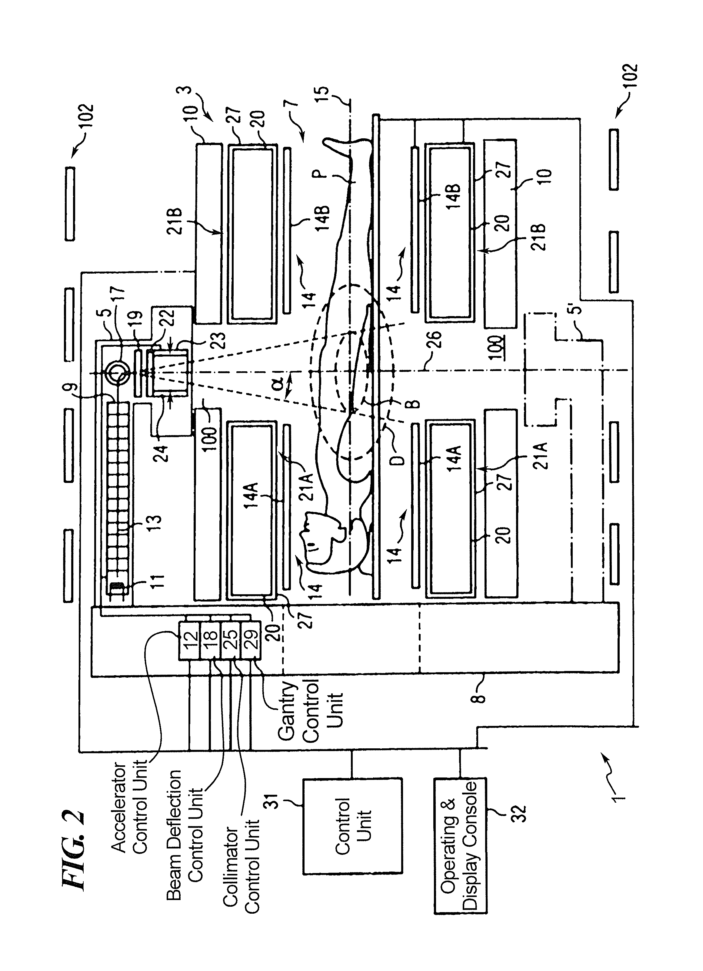
[0037]FIG. 2 shows a combined MRI and radiation therapy system 2 according to an embodiment of the present invention. Main magnet 10 is provided with “Letterbox” slots 100 through the cryostat and between coils of the main magnet to allow the radiation beam to reach a patient P at the irradiation center B. There may be some circumferential positions which are not available for passage of the radiation beam, for example where mechanical support pillars join the two parts of main magnet 50 together, but a good range of operation may be provided for without difficulty. LINAC 9, target 19 and collimator 23 are provided radially outside of the main magnet 10, but radially inside shield coils 102. In an embodiment of the invention, shield coils are placed inside the same cryostat as the main magnet, with a recess formed in the cryostat to accommodate the LINAC 9 and associated equipment. Gantry 8 is able to rotate about axis 15, enabling the radiation beam to be applied to the irradiation...


PUM


Abstract

A combined MRI and radiation therapy system has MRI imaging equipment and radiation therapy equipment. The MRI imaging equipment includes a shielded solenoidal magnet including a number of main magnet coils arranged coaxially along an axis, and a shielding arrangement arranged coaxially with the axis, at a greater radius from the axis than the main magnet coils. The radiation therapy equipment includes a LINAC assembly, that includes a linear electron accelerator arranged with an electron beam path parallel to the axis, and electron beam deflection arrangement and a target for generating a beam of therapeutic radiation. The linear electron accelerator is located at a position radially between the main magnet coils and the shielding arrangement.

Description

BACKGROUND OF THE INVENTION[0001]Field of the Invention[0002]The present invention relates to combined MRI and radiation therapy equipment.[0003]Description of the Prior Art[0004]Certain examples of combined MRI and radiation therapy equipment are known, but suffer from certain drawbacks. The present invention addresses at least some of those drawbacks.[0005]Radiation therapy typically uses gamma radiation, or similar, to target cancerous tissues in a patient. Such radiation may be generated either using an electron beam generated by an accelerator and aimed at a suitable target, or a radiation source containing a suitable radioactive isotope, such as cobalt-60.[0006]The use of a cobalt-60 source involves difficulties in storage, and prevention of over-exposure by operators. Screening of such sources can only be achieved by significant amounts of dense material such as lead or tungsten. Such sources are simple and are not affected by magnetic fields such as would be encountered in a...

Claims


Application Information

Patent Timeline
Patent Type & Authority Patents(United States)
IPC IPC(8): G01V3/00A61B5/055A61N5/10G01R33/48G01R33/421
CPCA61N5/1081A61B5/055A61N5/1049G01R33/4808A61N2005/1055G01R33/421A61N5/10A61N5/1039A61N5/1048G12B17/02
Inventor KRUIP, MARCEL
Owner SIEMENS HEALTHCARE GMBH
Why Eureka
Try Eureka