Fabric printing apparatus and heating device
a printing apparatus and fabric technology, applied in the direction of typewriters, transfer printing, textiles and paper, etc., can solve the problems of degrading the usability of fabric printers
- Summary
- Abstract
- Description
- Claims
- Application Information
AI Technical Summary
Benefits of technology
Problems solved by technology
Method used
Image

Examples
first embodiment
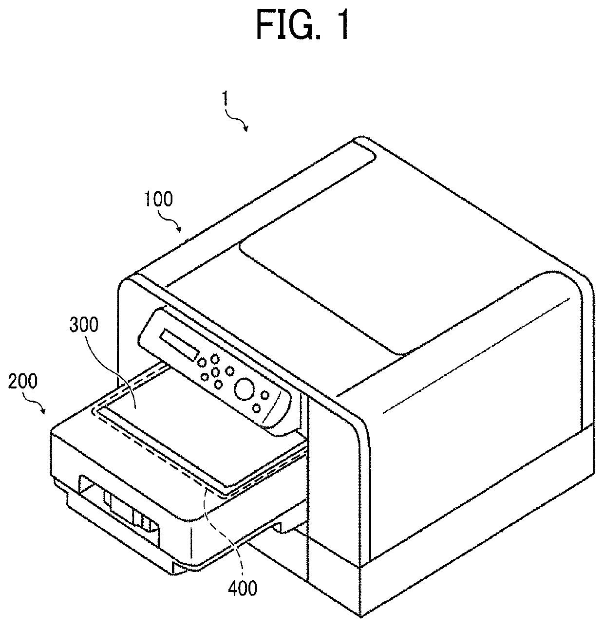
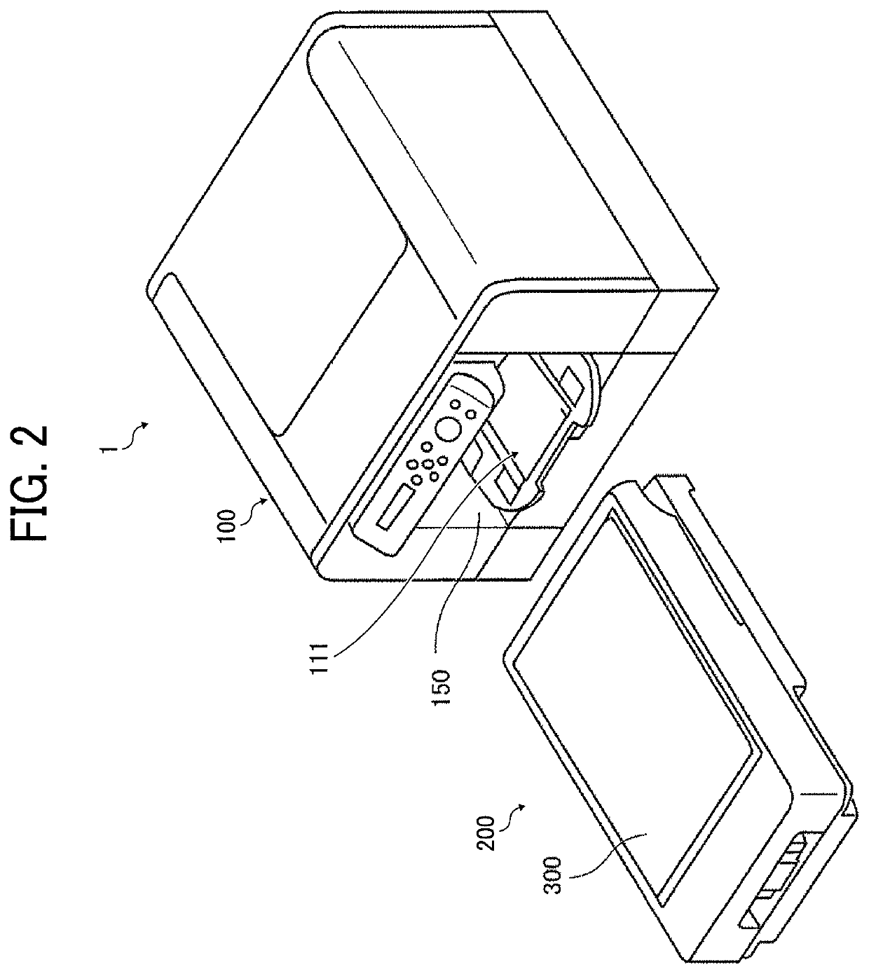
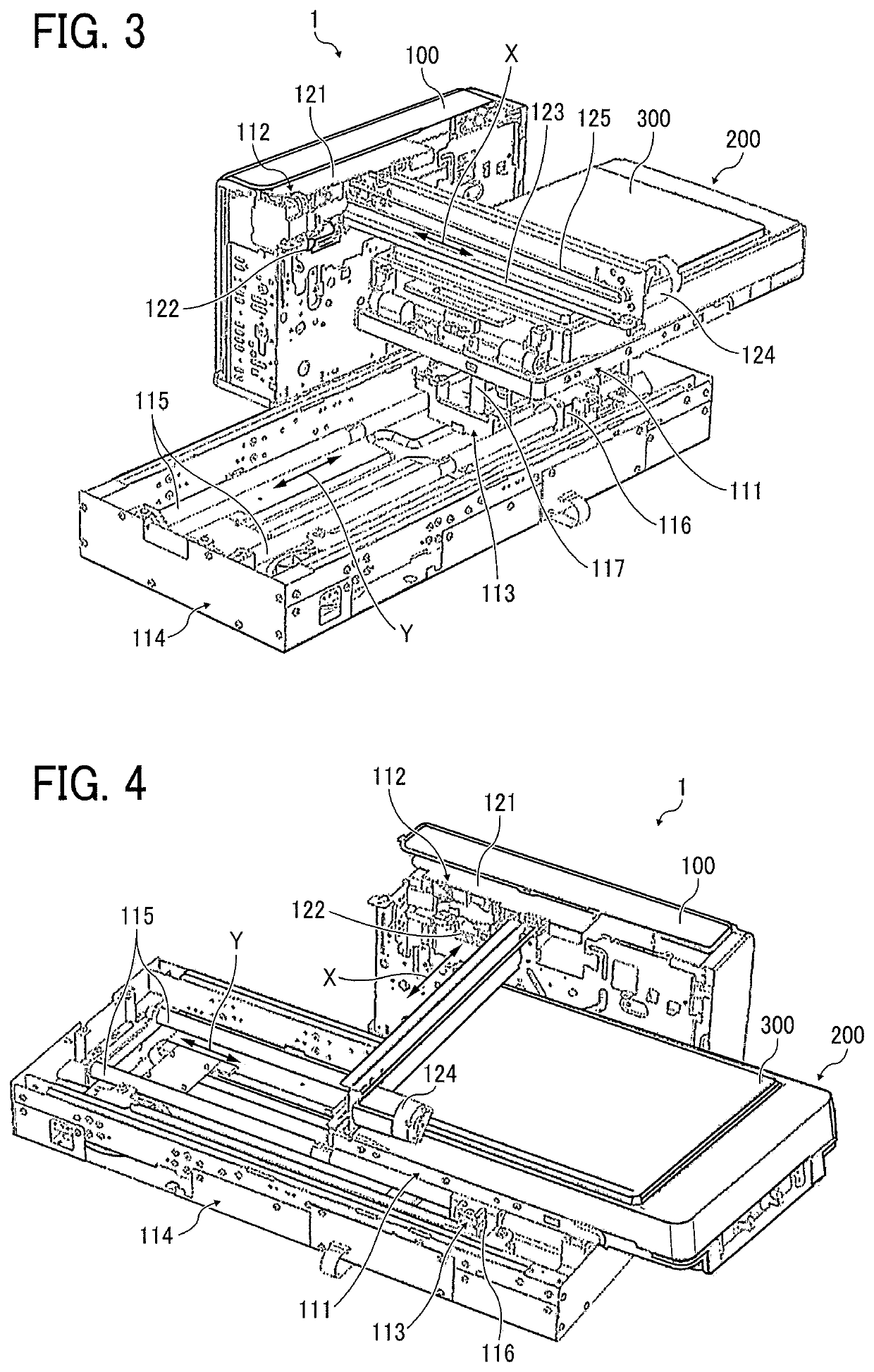
[0032]Referring to FIGS. 1 to 4, a description is provided of a construction of the printer 1 according to the present disclosure.
[0033]The printer 1 is a fabric printer serving as a fabric printing apparatus that prints on fabric. FIG. 1 is an external perspective view of the printer 1 attached with a cassette 200. FIG. 2 is an external perspective view of the printer 1 and the cassette 200 removed from the printer 1. FIG. 3 is an internal perspective view of the printer 1, illustrating an entire mechanical section thereof seen from a first direction. FIG. 4 is an internal perspective view of the printer 1, illustrating the entire mechanical section thereof seen from a second direction different from the first direction in FIG. 3.
[0034]As illustrated in FIGS. 1 to 4, the printer 1 serving as a fabric printing apparatus includes a body 100. Inside the body 100 are the cassette 200, a stage 111, and a printing device 112. As illustrated in FIG. 1, the cassette 200 serving as a cloth ...
second embodiment
[0059]Referring to FIGS. 12 to 16, a description is provided of a construction of a printer 1S according to a
[0060]FIG. 12 is a front view of the printer 1S according to a second embodiment. FIG. 13 is a perspective view of the printer 1S, seeing the printer 1S depicted in FIG. 12 from a diagonally right point. FIG. 14 is a perspective view of the printer 1S, seeing the printer 1S depicted in FIG. 12 from a diagonally left point. FIG. 15 is a perspective view of the cassette 200. FIG. 16 is a side view of the cassette 200 being attached to the body 100 of the printer 1S.
[0061]As illustrated in FIGS. 12 and 13, the printer 1S serving as a fabric printing apparatus includes guides 151 mounted on interior walls 100a of the body 100, respectively. The guides 151 guide the cassette 200 obliquely downward.
[0062]As illustrated in FIG. 15, projections 221 (e.g., bosses) are mounted on both side faces of the cassette base 201 of the cassette 200, respectively. As illustrated in FIG. 16, the ...
third embodiment
[0075]Referring to FIG. 18, a description is provided of a construction of a cassette 200S and a stage 111S installable in the printer 1 or 1S according to a
[0076]FIG. 18 is a diagram of the cassette 200S and the stage 111S.
[0077]As illustrated in FIG. 18, guide rails 131 are mounted on both lateral ends of the stage 111S in the direction perpendicular to the attachment direction DA, respectively. The cassette base 201 of the cassette 200S serving as a cloth holder includes both lateral ends 201a in the direction perpendicular to the attachment direction DA. The guide rails 131 are movably fitted onto or engaged with both lateral ends 201a of the cassette base 201 such that the guide rails 131 hold the lateral ends 201a, respectively.
[0078]Each of the lateral ends 201a of the cassette base 201 may be fitted into or engaged with the guide rail 131 entirely in the attachment direction DA. Alternatively, a projection locally disposed on each of the lateral ends 201a may be fitted into ...
PUM
| Property | Measurement | Unit |
|---|---|---|
| resilient | aaaaa | aaaaa |
| height | aaaaa | aaaaa |
| heat | aaaaa | aaaaa |
Abstract
Description
Claims
Application Information
 - R&D
- Intellectual Property
- Life Sciences
- Materials
- Tech Scout
- Unparalleled Data Quality
- Higher Quality Content
- 60% Fewer Hallucinations
Browse by: Latest US Patents, China's latest patents, Technical Efficacy Thesaurus, Application Domain, Technology Topic, Popular Technical Reports.
© 2025 PatSnap. All rights reserved.Legal|Privacy policy|Modern Slavery Act Transparency Statement|Sitemap|About US| Contact US: help@patsnap.com