Pressing device

a pressing device and battery technology, applied in the field of batteries, can solve problems affecting the quality of step-type cells, etc., and achieve the effect of improving the quality of batteries, simple structure of pressing devices, and easy operation

Active Publication Date: 2020-06-16
NINGDE AMPEREX TECH
View PDF12 Cites 0 Cited by
  • Summary
  • Abstract
  • Description
  • Claims
  • Application Information

AI Technical Summary

Benefits of technology

[0004]In view of the problem existing in the background of the present disclosure, an object of the present disclosure is to provide a pressing device, which can be adapted to a step type cell with a certain tolerance in thickness, and ensure that every step surface of the step cell is uniformly pressed, thereby improving the quality of a battery.
[0006]The present disclosure has the following beneficial effects: in the pressing device according to the present disclosure, the positioning member defines the position of each floating head so as to prevent the floating heads which are arranged side by side from swaying and loosening. When the pressing device works, each floating head is disposed on a corresponding step surface of a workpiece, then the cover plate is pressed down, due to the elastic member provided between the cover plate and each floating head, the cover plate can slide up and down relative to the floating head to realize that each floating head presses down the workpiece. The structure of the pressing device is simple and easy to operate, it can be adapted to a step type cell or a step type battery having a certain tolerance in thickness and can ensure that every step surface of the step type cell or the step type battery is uniformly pressed, thereby improving the quality of the battery.

Problems solved by technology

Generally, for a conventional non-step type cell, it often uses a flat-plate type pressing device to hot press; but for a new step type cell, it is common to add an outer vest fixed outside the step type cell and then perform pressing, because a height of each step of the outer vest is constant, when there is a tolerance in a thickness of each step of the step type cell, it cannot ensure uniform pressure, thereby affecting the quality of the step type cell.

Method used


Image

  • Pressing device
  • Pressing device
  • Pressing device

Examples


Embodiment Construction

[0035]A pressing device according to the present disclosure will be described in detail with referring to the figures.

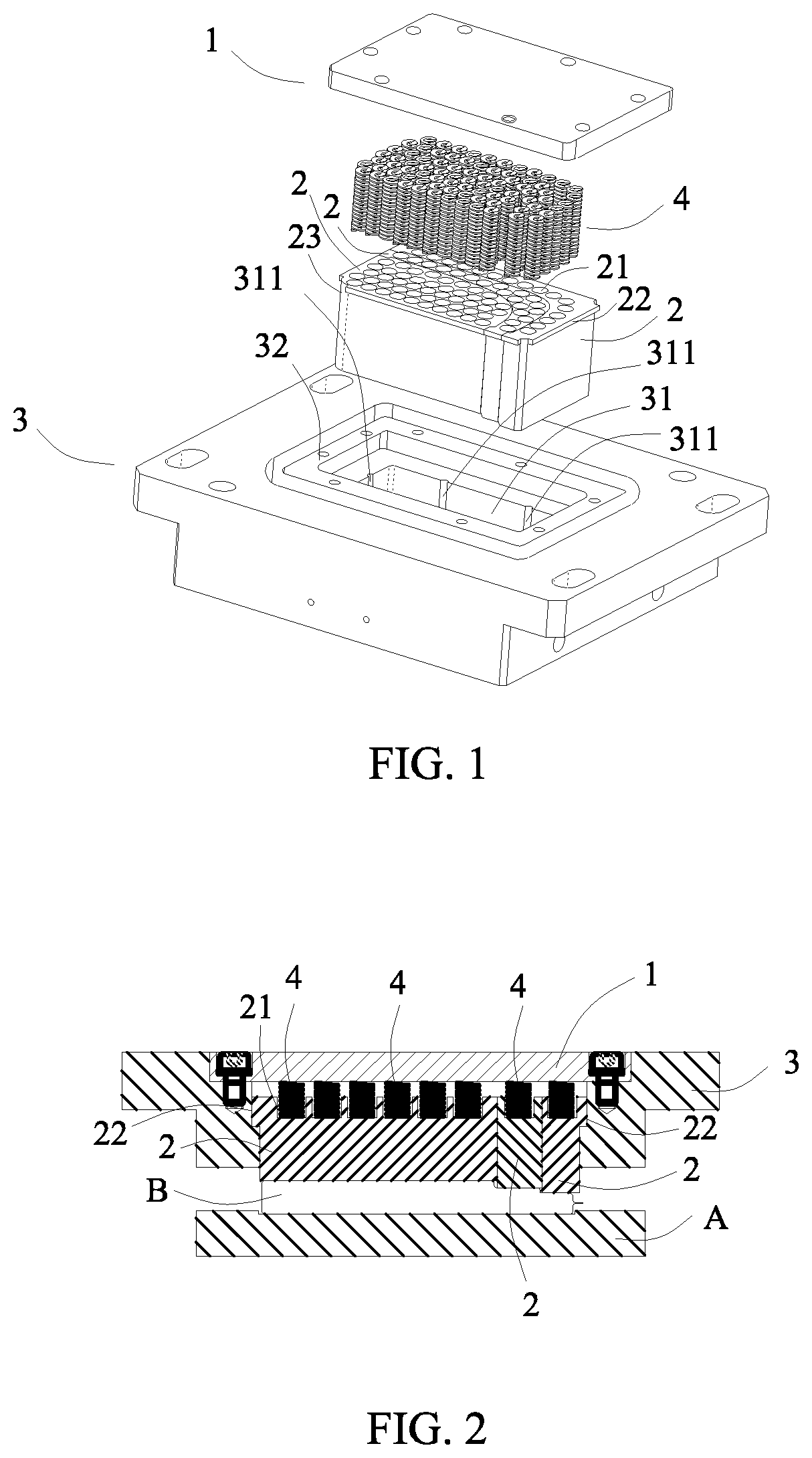
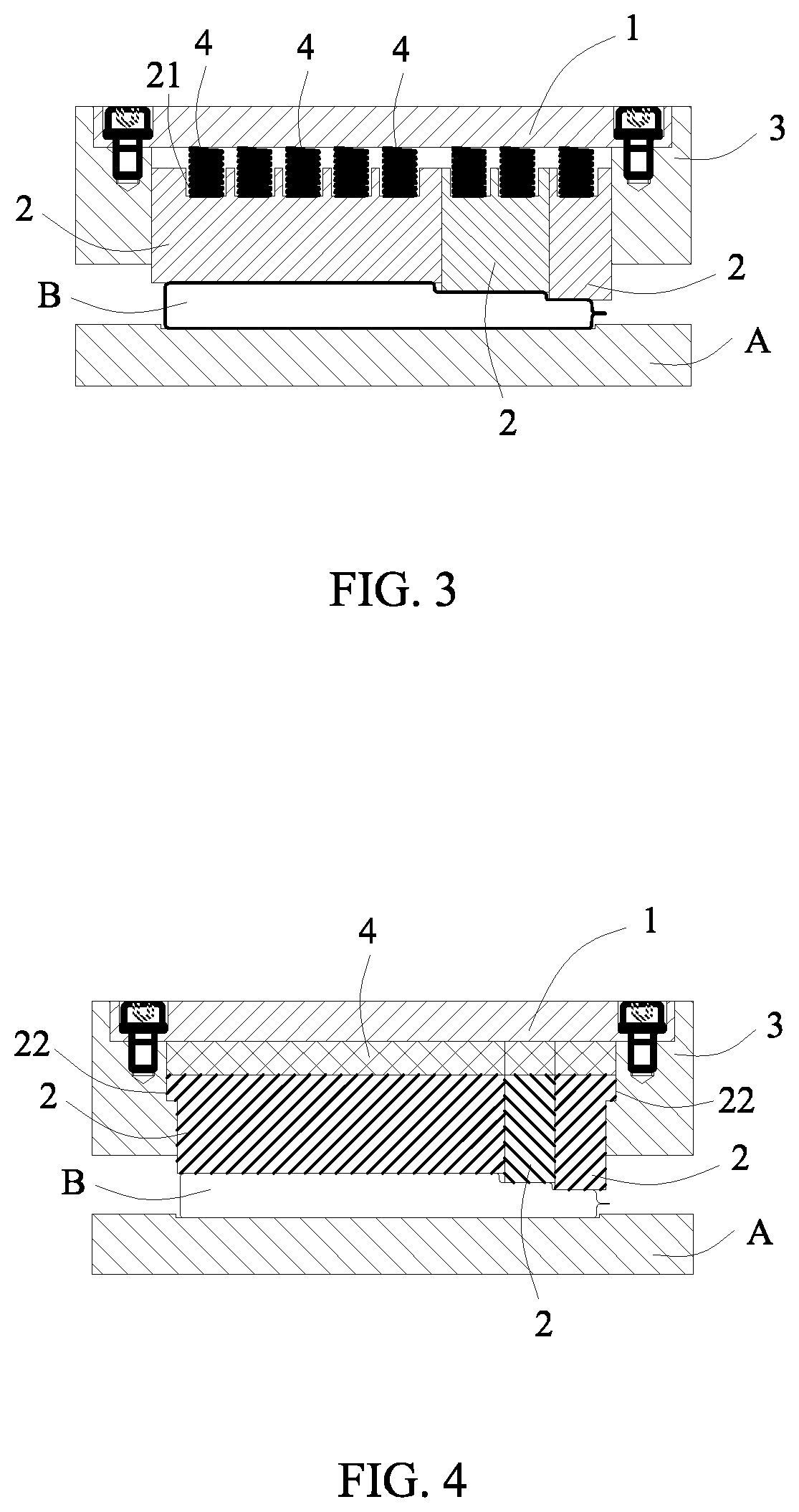
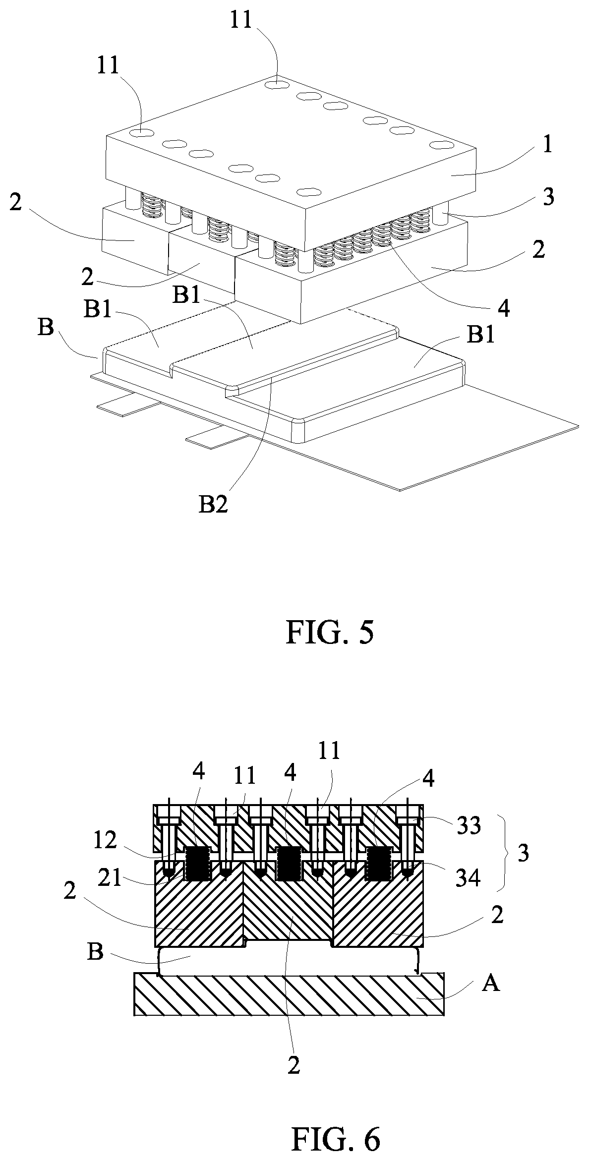
[0036]Referring to FIG. 1 to FIG. 10, a pressing device according to the present disclosure comprises: at least two floating heads 2 which are arranged side by side; a positioning member 3 connecting with each floating head 2 and defining a position of each floating head 2; a cover plate 1 positioned above each floating head 2; and elastic members 4, each elastic member 4 is provided between the cover plate 1 and the corresponding floating head 2, so as to make the cover plate 1 slide up and down relative to each floating head 2.

[0037]In the pressing device according to the present disclosure, the positioning member 3 defines the position of each floating head 2 so as to prevent the floating heads 2 which are arranged side by side from swaying and loosening. When the pressing device works, each floating head 2 is disposed on a corresponding step surface B1 of a workp...


PUM

PropertyMeasurementUnit
elasticaaaaaaaaaa
heightaaaaaaaaaa
thicknessaaaaaaaaaa

Abstract

The present disclosure provides a pressing device which includes: at least two floating heads which are arranged side by side; a positioning member connecting with each floating head and defining a position of each floating head; a cover plate positioned above each floating head; and elastic members, each elastic member being provided between the cover plate and the corresponding floating head so as to make the cover plate slide up and down relative to each floating head. The pressing device can be adapted to a step type cell or a step type battery having a certain tolerance in thickness and can ensure that every step surface of the step type cell or the step type battery is uniformly pressed, thereby improving the quality of the battery.

Description

REFERRING TO RELATED APPLICATIONS[0001]The present application claims priority to Chinese patent application No. 201620211570.X, filed on Mar. 18, 2016, which is incorporated herein by reference in its entirety.FIELD OF THE PRESENT DISCLOSURE[0002]The present disclosure relates to a field of battery, and specifically relates to a pressing device.BACKGROUND OF THE PRESENT DISCLOSURE[0003]In preparation of a battery, in order to make electrode plates better attached together to improve performance and quality of the battery, it needs to hot press a cell of the battery. Generally, for a conventional non-step type cell, it often uses a flat-plate type pressing device to hot press; but for a new step type cell, it is common to add an outer vest fixed outside the step type cell and then perform pressing, because a height of each step of the outer vest is constant, when there is a tolerance in a thickness of each step of the step type cell, it cannot ensure uniform pressure, thereby affect...

Claims


Application Information

Patent Timeline
Patent Type & Authority Patents(United States)
IPC IPC(8): B30B15/06H01M10/04H01M6/00
CPCB30B15/062H01M10/0481H01M6/005B30B15/065H01M10/0468B30B15/068Y02E60/10Y02P70/50
Inventor ZHOU, LIGANGDONG, YULONG
Owner NINGDE AMPEREX TECH
Why Eureka
Try Eureka