DC vacuum interrupter with multi-polar transverse permanent magnetic structure

a permanent magnetic structure, vacuum circuit breaker technology, applied in the direction of protective switch operating/release mechanism, magnets, magnetic bodies, etc., can solve the problems of inability to meet the requirements of vacuum interrupters with conventional contact and voltage features of vacuum arcs, and the structure is too complicated, etc., to promote a wide range of application of vacuum interrupters, low fault rate, and simple structure

Active Publication Date: 2020-06-23
XI AN JIAOTONG UNIV
View PDF6 Cites 0 Cited by
  • Summary
  • Abstract
  • Description
  • Claims
  • Application Information

AI Technical Summary

Benefits of technology

[0009]A DC vacuum interrupter with a permanent magnetic structure, comprises: a ceramic envelope (122), a permanent magnetic structure 201 at a fixed side outside of the ceramic envelope (122), a permanent magnetic structure 202 at a moving side outside of the ceramic envelope (122), a multi-polar magnetic core structure 103 at the fixed side inside of the ceramic envelope (122), a multi-polar magnetic core structure (106) at the moving side inside of the ceramic envelope (122), a cup-shaped transverse magnetic contact (102) at the fixed side and a cup-shaped transverse magnetic contact (107) at the moving side, wherein a multi-polar transverse magnetic field is generated in a gap between the cup-shaped transverse magnetic contact (102) at the fixed side and the cup-shaped transverse magnetic contact (107) at the moving side by the permanent magnetic structure (201) at the fixed side and the permanent magnetic structure at the moving side and the multi-polar magnetic core structure (103) at the fixed side and the multi-polar magnetic core structure 106 at the moving side; when an arc goes around a ring contact material (104) at the fixed side and a ring contact material (105) at the moving side in the gap, the arc cuts magnetic field lines of a transverse magnetic field generated by the permanent magnetic structure (201) and the permanent magnetic structure (202) and the multi-polar magnetic core structure (103) and the multi-polar magnetic core structure (106); an arc column moves rapidly between the gap under a magnetic force generated by the cup-shaped transverse magnetic contact (102) at the fixed side and the cup-shaped transverse magnetic contact (107) at the moving side during a high current arc-melting procedure; thus the transverse magnetic field generated by the permanent magnetic structure (201) at the fixed side and the permanent magnetic structure (202) at the moving side and the multi-polar magnetic core structure (103) at the fixed side and the multi-polar magnetic core structure (106) at the moving side acts on the arc for multiple times during the high current arc-melting procedure. The excitation system of the permanent magnet of the vacuum interrupter acts similar to the high frequency transverse magnetic field, which increases the arc voltage significantly.
[0020]A DC vacuum interrupter with a multi-polar transverse permanent magnetic structure, comprises a ceramic envelope (122), a permanent magnetic structure (201) at a fixed side outside of the ceramic envelope (122), a permanent magnetic structure 202 at a moving side outside of the ceramic envelope (122), a multi-polar magnetic core structure (103) at the fixed side inside of the ceramic envelope (122), a multi-polar magnetic core structure (106) at the moving side inside of the ceramic envelope (122), a cup-shaped transverse magnetic contact (102) at the fixed side and a cup-shaped transverse magnetic contact (107) at the moving side, wherein a multi-polar transverse magnetic field is generated in a gap between the cup-shaped transverse magnetic contact (102) at the fixed side and the cup-shaped transverse magnetic contact (107) at the moving side by the permanent magnetic structure (201) at the fixed side and the permanent magnetic structure at the moving side and the multi-polar magnetic core structure (103) at the fixed side and the multi-polar magnetic core structure (106) at the moving side; when an arc goes around a ring contact material (104) at the fixed side and a ring contact material (105) at the moving side in the gap, the arc cuts magnetic field lines of a transverse magnetic field generated by the permanent magnetic structure (201) and the permanent magnetic structure (202) and the multi-polar magnetic core structure (103) and the multi-polar magnetic core structure (106); an arc column moves rapidly between the gap under a magnetic force generated by the cup-shaped transverse magnetic contact (102) at the fixed side and the cup-shaped transverse magnetic contact (107) at the moving side during a high current arc-melting procedure; thus the transverse magnetic field generated by the permanent magnetic structure (201) at the fixed side and the permanent magnetic structure (202) at the moving side and the multi-polar magnetic core structure (103) at the fixed side and the multi-polar magnetic core structure (106) at the moving side acts on the arc for multiple times during the high current arc-melting procedure. The excitation system of the permanent magnet of the vacuum interrupter acts similar to the high frequency transverse magnetic field, which increases the arc voltage significantly. The present invention achieves the goal of DC breaking and is able to be applied in situation needs high arc voltage. The present invention takes the effects of the high frequency transverse magnetic field on the vacuum arc voltage into account and takes full advantages of the high speed circle movement of the vacuum arc during arc burning. The present invention further brings about a delicate magnetic circuit design of the transverse magnetic field and successfully realizes a multi-polar design of the transverse magnetic field by the multi-polar permanent magnets. The present invention increases the vacuum arc voltage and promotes the applications in DC on / off in the vacuum circuit breaker which adopts the vacuum interrupter.
[0021]The present invention has the following advantages comparing with the conventional technology.
[0022]1) High frequency transverse magnetic field is put on the vacuum arc. The present invention takes advantage of the arc turning around rapidly on the surface of the contact and successfully improves arc voltage of the vacuum interrupter. The vacuum breaker in DC circuit adopts the vacuum interrupter in the present invention is possible.
[0024]3) The present invention is simple in structure with low fault rate and is able to promote a wide application of the vacuum interrupter in industrial filed.

Problems solved by technology

With a development of electric car, solar power and the mature of the vacuum arc technology, how to apply the vacuum circuit breaker to DC field becomes a huge challenge and forms a huge demand.
The vacuum interrupter with the conventional contact and the voltage feature of the vacuum arc are incapable of meeting the requirements.
To put high frequency transverse magnetic field on the vacuum arc is rather easy in a lab except for the structure is too complicate.
The method is limited in the lab and keeps from application in the industrial field due to the over-complicate structure and power circuit, though the method meets the predicted requirement of the design.

Method used


Image

  • DC vacuum interrupter with multi-polar transverse permanent magnetic structure
  • DC vacuum interrupter with multi-polar transverse permanent magnetic structure
  • DC vacuum interrupter with multi-polar transverse permanent magnetic structure

Examples


Embodiment Construction

[0035]Referring to the drawings, the present invention is described in detail with the embodiments.

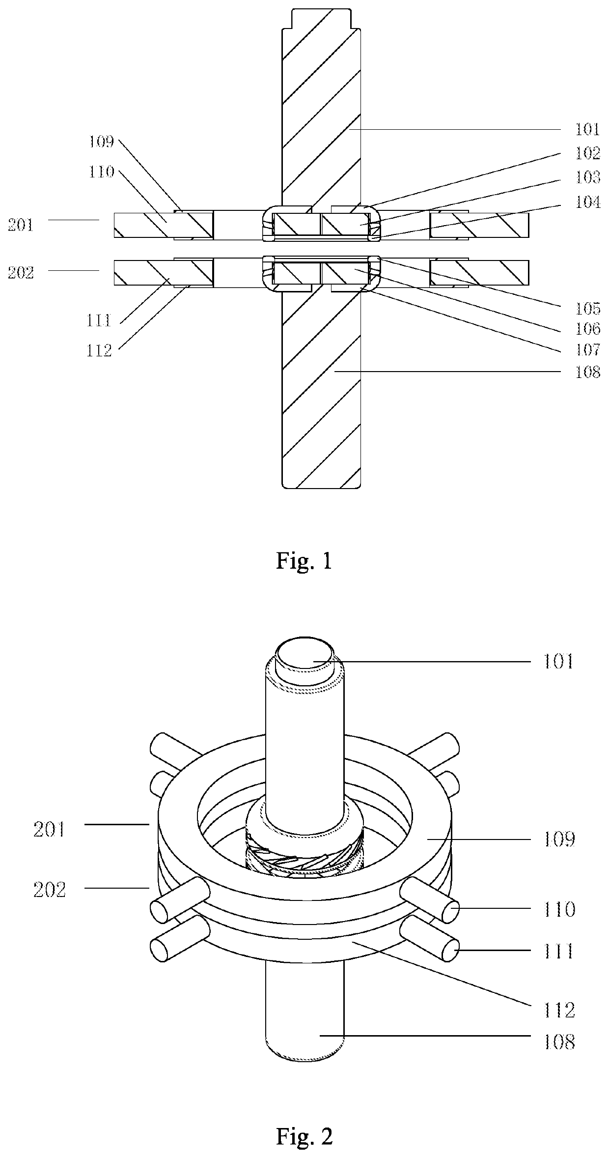
[0036]FIG. 1 and FIG. 2 are a cross-section view along the axial and the side view of a DC vacuum interrupter contacts and a permanent magnetic excitation structure of a four-polar transverse permanent magnetic structure of the present invention of a multi-polar DC vacuum interrupter with a transverse permanent magnetic structure. As shown in the FIG. 1 and FIG. 2 the fixed side structure further comprises a conducting rod 101, wherein the cup-shaped transverse magnetic contact 102 at the fixed side is welded on the bottom of the conducting rod 101; the ring contact material 104 at the fixed side is welded on the bottom of the cup-shaped transverse magnetic contact 102; the multi-polar magnetic core structure 103 is welded on the inner bottom of the cup-shaped transverse magnetic contact 102 of the fixed side; the welding surface of the ring contact material 104 is more protruding than...


PUM

PropertyMeasurementUnit
vacuum arc voltageaaaaaaaaaa
frequencyaaaaaaaaaa

Abstract

The present application discloses a DC vacuum interrupter. The cup-shaped contact of the vacuum interrupter is in a transverse magnetic field. The magnetic core is placed in the contact cup. The magnetic core inside the cup of the contact works with the permanent magnets outside the vacuum interrupter to generate transverse magnetic fields in multiple directions between the contacts. While the contacts are open, the arc burns and moves rapidly along the ring shaped contacts under the transverse field along the tangent line of the contacts. While the arc moves rapidly along the ring-shaped contacts, the arc column passes the permanent magnets structure and works with the magnetic core to generate multi-polar transverse magnetic field. While the arc column makes a turn, the number of the transverse fields which are cut by the arc is same with the number of the permanent magnets set.

Description

CROSS REFERENCE OF RELATED APPLICATION[0001]This application claims priority under 35 U.S.C. 119(a-d) to CN 2018102439505, filed Mar. 23, 2018.BACKGROUND OF THE PRESENT INVENTIONField of Invention[0002]The present invention relates to vacuum circuit breaker and DC vacuum interrupter field, and more particularly to DC vacuum interrupter with a multi-polar transverse permanent magnetic structure and the application thereof.Description of Related Arts[0003]The vacuum interrupter develops rapidly with a wide application in AC transmission and distribution system. With a development of electric car, solar power and the mature of the vacuum arc technology, how to apply the vacuum circuit breaker to DC field becomes a huge challenge and forms a huge demand.[0004]There are two types of vacuum arc technology in the conventional vacuum circuit breaker application in AC system, which are TMF (transverse magnetic field) and AMF (axial magnetic field). The TMF induces transverse magnetic field v...

Claims


Application Information

Patent Timeline
Patent Type & Authority Patents(United States)
IPC IPC(8): H01H33/66H01H71/12H01F7/02H01F7/16
CPCH01F7/02H01H33/66H01F7/1646H01H71/12H01H33/6642H01H33/182H01H9/443
Inventor MA, HUILIU, ZHIYUANWANG, JIANHUAGENG, YINGSANYI, XIULIXIAO, XIANGWENSHEN, JINYU
Owner XI AN JIAOTONG UNIV
Why Eureka
Try Eureka