Check patentability & draft patents in minutes with Patsnap Eureka AI!

Railcar-mover vehicle

a technology of a vehicle and a carriage, which is applied in the direction of transportation and packaging, railway components, and retractable wheels, etc., can solve the problems of over-hourly operation of the road-rail unit, frequent tire replacement, and high cost of premature replacement or major overhaul of the transmission uni

Active Publication Date: 2020-06-30
CUSTOM TRUCK & EQUIP
View PDF56 Cites 1 Cited by
  • Summary
  • Abstract
  • Description
  • Claims
  • Application Information

AI Technical Summary

Benefits of technology

[0005]The railcar-mover vehicle was developed out of a need for a vehicle for moving railcars, which would satisfy the requirements of today's rail industry. While other products are currently in existence for performing the functions of the railcar-mover vehicle the vehicle disclosed herein improves on well-known weaknesses and problem areas in the existing market.
[0006]The vehicle disclosed herein comprises at its core a modified commercial truck. The railcar-moving vehicle is capable of operation on roadways and operation on rails. The railcar-moving vehicle includes a support system with a front end and a rear end, at least one drive axle with two rubber drive tires, and at least one pair of steering tires as well as a sled frame slidably mounted to the support system that is translatable between the front end and the rear end of the support system. The railcar-mover vehicle is optimized to provide a high level of reliable tractive effort while moving railcars.
[0009]In a second operational configuration of the vehicle, the rubber drive tires remain in contact with the rails when starting movement to provide additional traction, beyond that provided by the front and rear bogies in order to pull more railcars or to pull more heavily loaded railcars. It is during the initiation of movement of the railcar-mover vehicle heavily laden with one or more railcars that the greatest traction between the wheelsets and the rails is required. Once the load is started, the operator may choose to raise the rubber tires to the preferred operational configuration to lessen their wear.
[0010]In a third operational configuration of the vehicle, the bogies and rubber drive tires initiate movement of the towed railcars thereby maximizing the pulling power of the vehicle. As the vehicle gains speed the drive motors in the bogies are disengaged and the bogie wheelsets freewheel along the rails with tractive power provided solely by the rubber drive tires. This operational configuration is generally least preferred as it results in operation with the same weaknesses as the current art. That is, it places the greatest stress on the truck transmission and the rubber drive tires. This configuration; however, achieves the highest rail speed as the rubber drive tires, with the bogie wheelsets disengaged, are capable of propelling the vehicle at the greatest speed along the rails and may be advantageous for transit or emergency operations with no cargo load.
[0011]The sled frame's function is to aid in optimizing weight distribution over the bogies of the railcar mover, depending on operational conditions. The operator of the railcar mover vehicle optimizes weight distribution, and consequently traction, by repositioning the movable sled frame and the associated operational equipment mounted thereon. For example, in moving one or more heavily loaded railcars, the sled frame and associated equipment are moved rearward or forward as necessary to apply additional weight over a specific bogie. The sled frame may be moved anywhere along the range of the sled.
[0012]One of the primary objectives of the sled frame is to place as much weight onto the bogie system wheels as possible during rail operation to eliminate, or at least minimize, slippage between the wheels and the rail when the forward and rear bogie wheelsets are placed into drive mode. If, for example, the rear bogie wheels are slipping on the rails due to the load of one or more railcars, then the sled frame and associated equipment mounted thereon can be moved to apply additional weight anywhere along the range of the sled.

Problems solved by technology

Multi-purpose vehicles that are capable of towing railcars and that rely upon the use of the rubber road tires to maintain contact with the rails to provide motive power tend to require frequent tire replacement due to extreme abrasion of a narrow portion of the tires because of slippage on the rails.
In addition, vehicles configured for towing that are driven by the rubber road tires on the rails tend to regularly overheat the vehicle transmission resulting in costly premature replacement or major overhauls of the transmission units.
The utilization of a switching locomotive and one or more engineers to travel to the location of the railcar or locomotive that must be shuttled to a repair facility greatly exceeds the hourly cost of operation of a road-rail unit.
Costs associated with retrieval, or a repair operation can mount quickly if the location of the railcar, locomotive or railway in need of repair is distant and requires considerable transit time.
This operational configuration is generally least preferred as it results in operation with the same weaknesses as the current art.

Method used


Image

  • Railcar-mover vehicle
  • Railcar-mover vehicle
  • Railcar-mover vehicle

Examples


Embodiment Construction

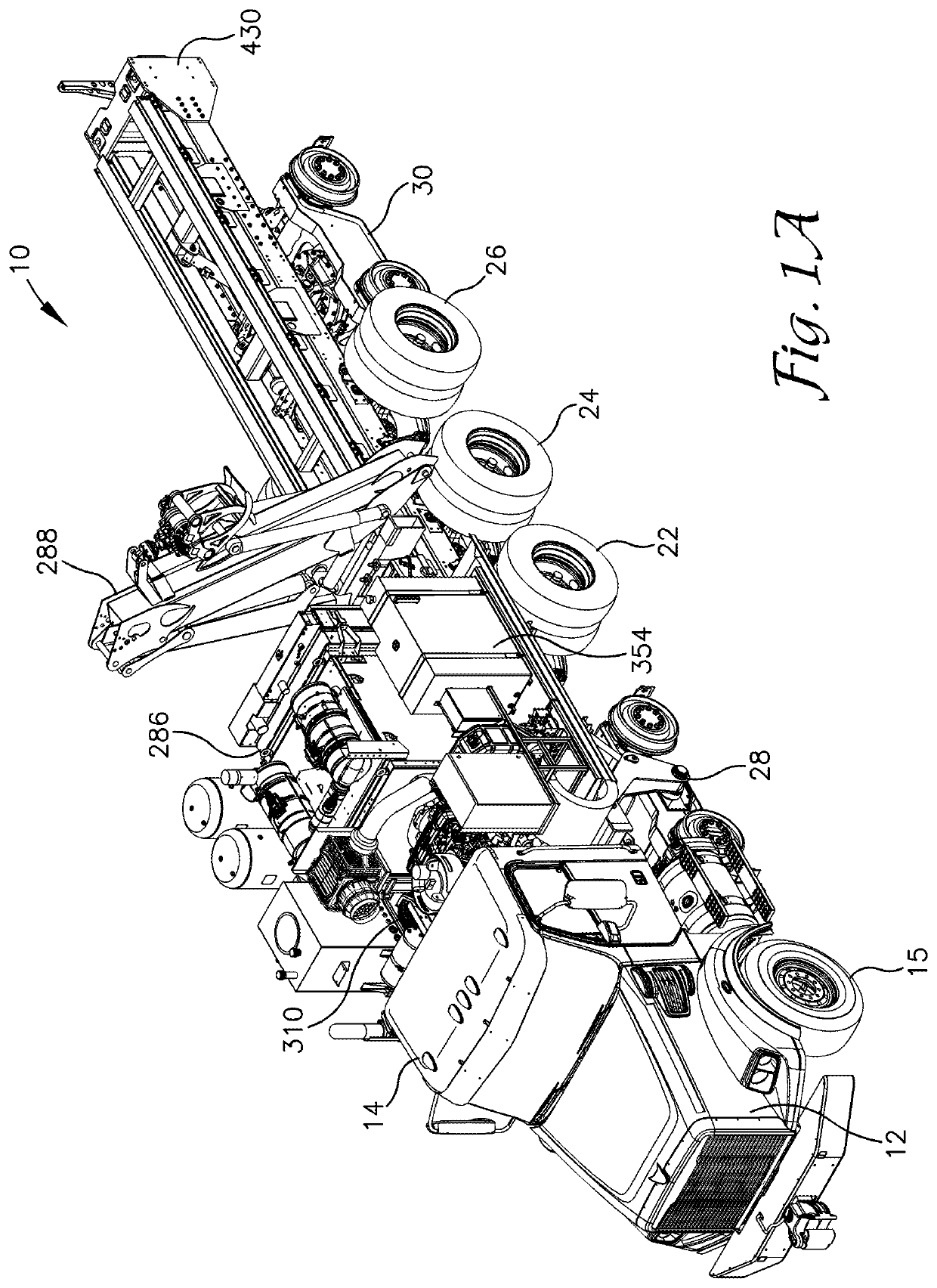
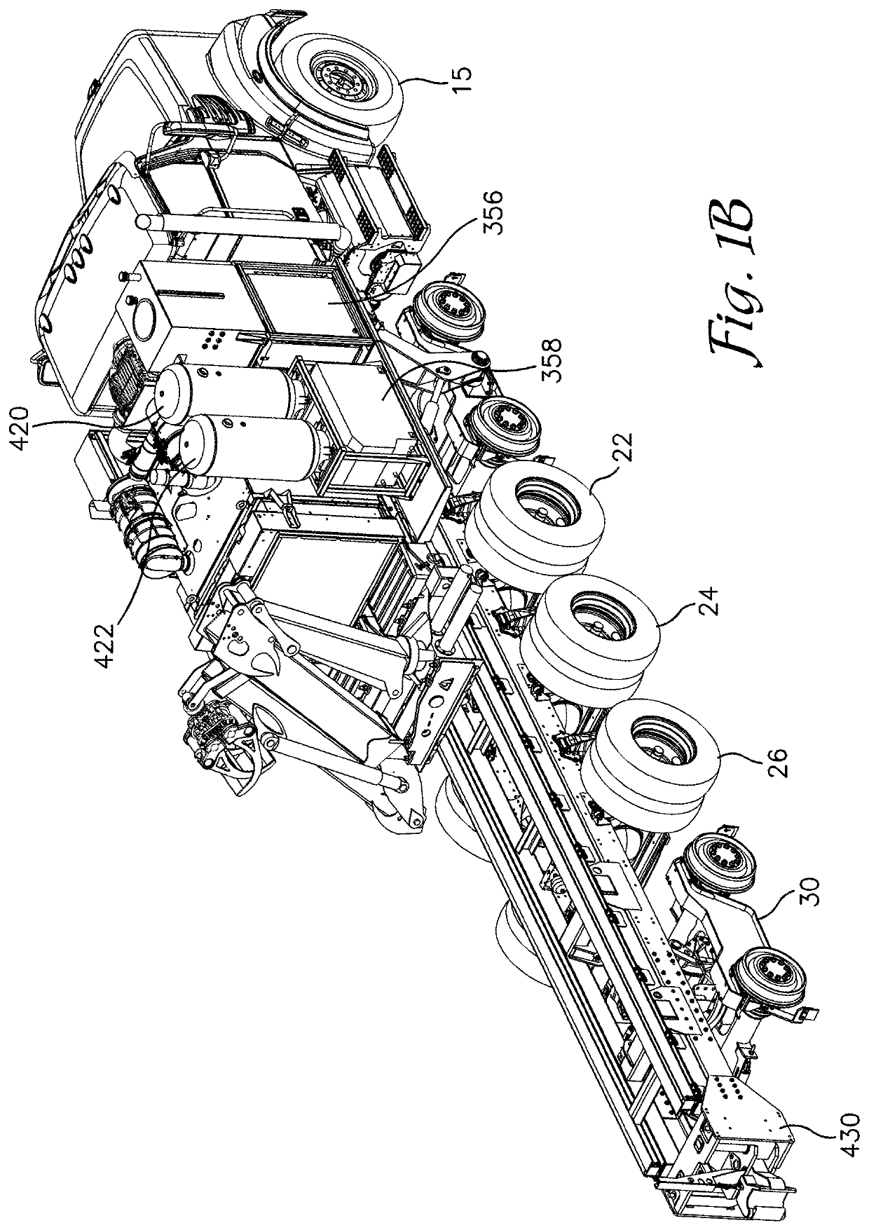
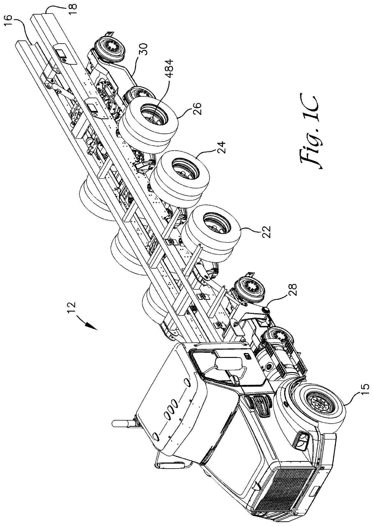
[0041]For purposes of assisting in the identification of the location of various components described herein the cab area of the disclosed railcar mover vehicle will be termed the front end of the vehicle and the distal ends of the frame rails, fully opposite the cab, is identified as the rear end of the railcar mover vehicle. Future references to front and rear throughout this description will provide the reader with a frame of reference as to the location of the component relative to other components.

[0042]The foundation of the railcar mover vehicle 10 described herein begins with a conventional straight truck 12 purchased from vendors such as Freightliner®, Peterbilt® and other companies that specialize in the production of straight trucks. The railcar mover vehicle is custom assembled, or “upfitted,” upon the conventional straight truck. Exemplary embodiment(s) of the vehicle 10 are described below with reference to the attached drawings. While on road the railcar mover is power...


PUM


Abstract

Disclosed herein is a railcar-moving vehicle having a highway mode for operation on roadways, and a rail mode for operation on rails. The railcar-moving vehicle including a support system, at least one drive axle with rubber tried drive wheels, and at least one pair of steering tires and two spaced apart rail bogies suspended by the support system. The railcar-moving vehicle including a weighted sled frame slidably mounted to the support system, the sled frame translatable between the front end and the rear end of the support system for optimizing weight distribution for increasing traction by the bogies when in rail mode. The bogies retained in an elevated and stowed position during highway mode and in a lowered position when in rail mode.

Description

TECHNICAL FIELD[0001]This disclosure relates to a road-rail vehicle. More particularly, it relates to an improved road-rail vehicle capable of traveling by road at normal highway speeds as well as traveling by rail.BACKGROUND ART[0002]Road-rail vehicles which are operable on both roadways and highways are known and used in the rail industry for ferrying railcars from one location to the next. Units capable of self-propulsion on both highways and railways which embody a source of power for movement and which are also configured to provide for the selective attachment, support and conveyance of various types of maintenance equipment so the one unit may be universally applicable for carrying out a wide variety of maintenance and construction operations are in great demand by the railroad industry. In addition, these road-rail vehicles are highly desirable when they are capable of coupling and moving railcars, or even locomotives, that are sidelined due to maintenance issues or for othe...

Claims


Application Information

Patent Timeline
Patent Type & Authority Patents(United States)
IPC IPC(8): B61F1/04B60F1/04B60F1/00
CPCB60F1/005B60F1/043B60F2301/04B60F2301/10
Inventor LANG, SCOTT ALLENTHELWELL, DWIGHT JOHANNES
Owner CUSTOM TRUCK & EQUIP
Features
  • R&D
  • Intellectual Property
  • Life Sciences
  • Materials
  • Tech Scout
  • Unparalleled Data Quality
  • Higher Quality Content
  • 60% Fewer Hallucinations
Learn More