Transmitting and receiving circuit

a technology of receiving circuit and transmitting circuit, which is applied in the direction of frequency-division multiplex, selective content distribution, emergency protective arrangements for limiting excess voltage/current, etc., can solve the problem of harmonic distortion, inability to use tvs, and the dielectric breakdown of a device included in the transmitting and receiving circuit. problems, to achieve the effect of eliminating harmonic distortion and easy cause harmonic distortion

Active Publication Date: 2020-06-30
MURATA MFG CO LTD
View PDF12 Cites 0 Cited by
  • Summary
  • Abstract
  • Description
  • Claims
  • Application Information

AI Technical Summary

Benefits of technology

[0012]Preferred embodiments of the present invention appropriately protect a semiconductor switch for switchover from a leakage surge voltage without influencing transmitted and received signals, the semiconductor switch being included in a transmitting and receiving circuit for CATV.
[0021]According to a preferred embodiment of the present invention, in a transmitting and receiving circuit for CATV including a semiconductor switch, a ceramic-based electro-static discharge protector that does not easily cause harmonic distortion is preferably used as an electro-static discharge protection circuit. This eliminates the need for additionally providing a filter to eliminate harmonic distortion, unlike a semiconductor-based electro-static discharge protection circuit, such as a TVS. Accordingly, it is possible to appropriately protect the semiconductor switch from a leakage surge voltage without influencing transmitted and received signals.

Problems solved by technology

If the lightning surge as described above enters the STB, there is a possibility of a dielectric breakdown of a device included in the transmitting and receiving circuit.
However, a semiconductor-based protection circuit, such as the TVS, has non-linear load characteristics, and thus, using the semiconductor-based protection circuit for a high frequency signal might lead to harmonic distortion caused by a harmonic with a frequency that is an integer multiple of the frequency of a passing signal.
Accordingly, it is not possible to use the TVS under the circumstances as described above and, thus, not possible to appropriately protect the semiconductor switch for switchover from the leakage surge voltage.

Method used


Image

  • Transmitting and receiving circuit
  • Transmitting and receiving circuit
  • Transmitting and receiving circuit

Examples


Embodiment Construction

[0031]Hereinafter, preferred embodiments of the present invention will be described in detail with reference to the drawings. Note that the same or equivalent components in the drawings are denoted by the same reference numerals, and description thereof is not repeated.

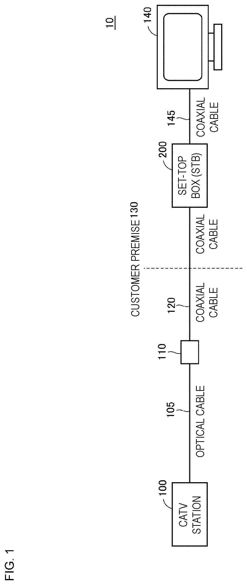
[0032]FIG. 1 is an overall schematic diagram of a CATV system including a STB 200 including a transmitting and receiving circuit according to a preferred embodiment of the present invention.

[0033]In FIG. 1, the CATV system 10 transfers a transmitted signal, such as a television signal transmitted from a CATV station 100, to a customer premise 130 through an optical cable and coaxial cables. The transferred transmitted signal is received by the STB 200 and undergoes branching filter processing, and video is displayed on a display device 140, such as a television receiver, a monitor, or other suitable display device.

[0034]The CATV system 10 is also used for a network for the Internet. In this case, the CATV system 10 tr...


PUM


Abstract

A transmitting and receiving circuit that transmits and receives signals using coaxial cables includes an input / output terminal that delivers and receives signals, a first port, a second port, a switch, and a ceramic-based electro-static discharge protector. The first port transfers a transmitted signal in a first transmission frequency band width and a received signal in a first reception frequency band width. The second port transfers a transmitted signal in a second transmission frequency band width and a received signal in a second reception frequency band width. The switch connects a common port to one of the first port and the second port. The common port is connected to the input / output terminal on one end of the common port and to the switch on the other end. The electro-static discharge protector is connected between the common port and the ground potential.

Description

CROSS REFERENCE TO RELATED APPLICATIONS[0001]This application claims the benefit of priority to Japanese Patent Application No. 2017-035738 filed on Feb. 28, 2017. The entire contents of this application are hereby incorporated herein by reference.BACKGROUND OF THE INVENTION1. Field of the Invention[0002]The present invention relates to a transmitting and receiving circuit and particularly relates to electro-static discharge (ESD) protection in a transmitting and receiving circuit.2. Description of the Related Art[0003]Cable television (CATV) systems that transmit and receive television signals and the like by using wired communication lines have been known, and some CATV systems use a wiring system called a hybrid fiber-coaxial (HFC) system. In the HFC system, an optical cable is used for wiring from a CATV station to the trunk portion of a transmission line, and a coaxial cable is used for wiring for a branch line portion from the trunk to each of customer premises.[0004]In a CATV...

Claims


Application Information

Patent Timeline
Patent Type & Authority Patents(United States)
IPC IPC(8): H02H7/20H04N21/40H04J1/08H04H20/78H04J1/04H04B1/40H04H40/27H04N21/61H04B1/04H02H9/04H01C8/04
CPCH04J1/08H01C8/04H04H20/78H04B1/40H04B1/0466H04N21/40H02H7/20H04J1/045H04N21/615H02H9/041H04H40/27
Inventor MORI, TAKAHIROWASHIMORI, TADASHI
Owner MURATA MFG CO LTD
Why Eureka
Try Eureka