A mems thermal microphone and its implementation method

A microphone and substrate technology, which is applied in the field of microelectronic mechanical sensing, can solve the problems of phase difference between sound pressure and vibration velocity signals, different manufacturing processes, and inability to ensure the common point of the sound center, so as to eliminate harmonic distortion. Effect

Active Publication Date: 2022-03-25
PEKING UNIV
View PDF4 Cites 0 Cited by
  • Summary
  • Abstract
  • Description
  • Claims
  • Application Information

AI Technical Summary

Problems solved by technology

[0004] When two sensors are assembled together, the sound center cannot be guaranteed to be at the same point, and the measured sound pressure and vibration velocity signals will have a phase difference;
[0005] Traditional piezoelectric and capacitive microphones are difficult to achieve single-chip integration with thermal acoustic particle vibration velocity sensors due to different manufacturing processes

Method used


Image

  • A mems thermal microphone and its implementation method
  • A mems thermal microphone and its implementation method
  • A mems thermal microphone and its implementation method

Examples


Embodiment 1

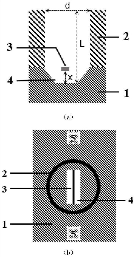
[0050] Such as figure 1 As shown, the upper cover plate of this embodiment adopts a cylindrical shape, and the MEMS thermal microphone of this embodiment includes: a substrate 1, a sensitive beam 3, an electrode 5, a back cavity 4, an upper cover plate 2 and a temperature measuring circuit; wherein, The substrate is made of hard material; a back cavity is set on the upper surface of the substrate; the two ends of the sensitive beam are erected on the edge of the back cavity on the upper surface of the substrate, and the sensitive area of ​​the sensitive beam is located on the back cavity; on the upper surface of the substrate Two electrodes are set on the part without the back cavity; the two ends of the sensitive beam are respectively connected to an electrode, and the two electrodes are connected to the external temperature measuring circuit; an upper cover is arranged on the back cavity on the upper surface of the substrate, and the upper cover The inner surface of the inne...

Embodiment 2

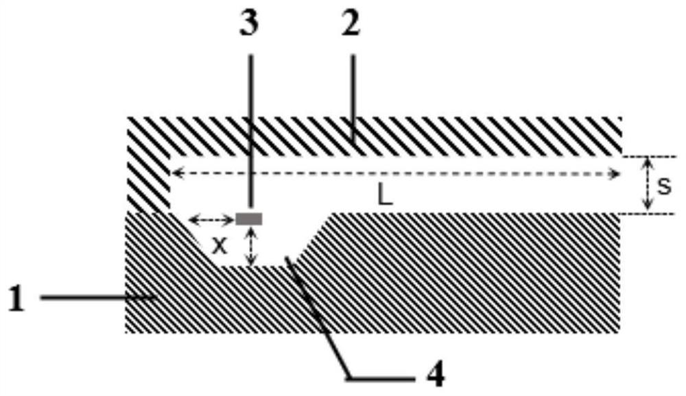
[0052] Such as figure 2 As shown, the upper cover plate of this embodiment adopts a cover shape, and one side of the cover-shaped upper cover plate is located at the outer edge of the back cavity and is sealingly connected with the upper surface of the substrate. Above and parallel to the upper surface of the substrate, the other side has a distance from the upper surface of the substrate to form an opening, as the nozzle of the standing wave tube, the distance s between the inner surface of the top wall and the upper surface of the substrate is less than 8.5mm. The upper cover adopts a cover shape, the bottom surface of the back cavity and the side surface facing the nozzle of the standing wave tube both constitute the tube bottom of the standing wave tube, the distance between the sensitive beam and the bottom surface of the back cavity and the distance between the sensitive beam and the back cavity The distance between the side surface of the nozzle of the standing wave t...


PUM


Abstract

The invention discloses a MEMS thermal microphone and a realization method thereof. In the present invention, a back cavity is formed on the substrate, the sensitive beam is placed on the back cavity, and an upper cover plate is arranged on the back cavity to form a standing wave tube; the sound wave enters the standing wave tube from the nozzle of the standing wave tube, and the sound pressure changes The temperature on the sensitive beam is disturbed; at the same time, the sound wave is reflected on the bottom of the standing wave tube, that is, the surface of the back cavity to form a standing wave. The sound pressure at the beam is twice the incident sound pressure at the nozzle of the standing wave tube, so the temperature of the sensitive beam is only proportional to the incident sound pressure, and will not be affected by the vibration velocity of the acoustic particles, eliminating harmonic distortion; The structure of the microphone is similar to that of the thermal acoustic particle velocity sensor, the manufacturing process is the same, and the measurement of sound pressure and acoustic particle velocity can be completed on the same chip.

Description

technical field [0001] The invention relates to microelectromechanical sensing technology, in particular to a MEMS thermal microphone and its realization method. Background technique [0002] Sound is the vibration propagation of medium molecules, the density of the medium corresponds to the change of sound pressure, and the vibration speed of medium molecules corresponds to the vibration velocity of sound particles. Sound pressure is a scalar quantity and can be measured directly with a microphone, while the vibration velocity of sound particles is a vector. Currently, the most effective detection method is based on the thermal principle. The thermal acoustic vector sensor consists of a heating beam and a temperature measuring beam. The heating beam provides a stable thermal field distribution. The temperature measuring beam perceives the disturbance of the thermal field when the acoustic particle vibrates, and measures the vibration velocity of the acoustic particle throug...

Claims


Application Information

Patent Timeline
Patent Type & Authority Patents(China)
IPC IPC(8): H04R19/00H04R19/04
CPCH04R19/005H04R19/04H04R2201/003
Inventor 朱哲政杨凌濛杨振川高成臣郝一龙
Owner PEKING UNIV
Why Eureka
Try Eureka