Circuit for removing harmonic distortion in sampling and retaining circuit
A harmonic distortion and holding circuit technology, applied in the direction of physical parameter compensation/prevention, can solve problems such as limiting the useful voltage range of input signals, distortion, and limiting the useful frequency range of input signals
- Summary
- Abstract
- Description
- Claims
- Application Information
AI Technical Summary
Problems solved by technology
Method used
Image
Examples
Embodiment Construction
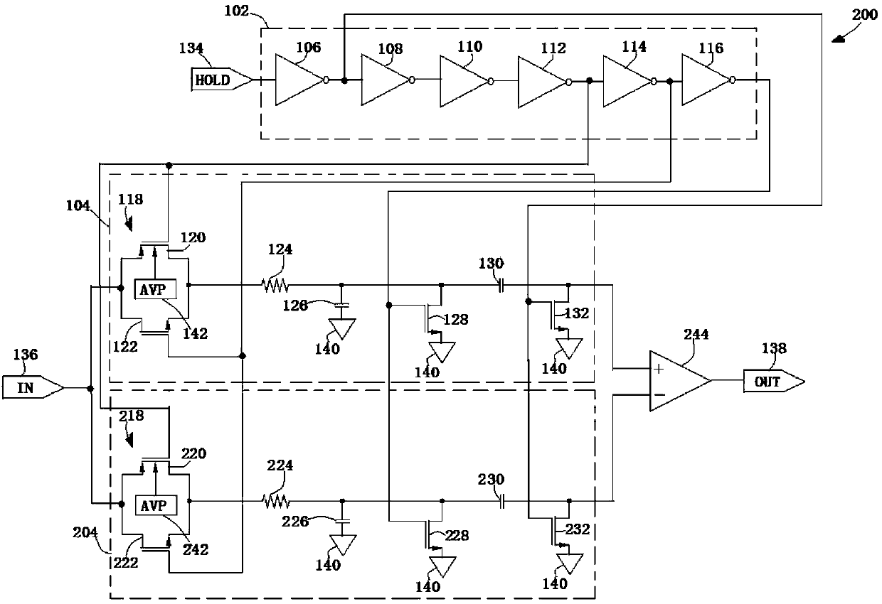
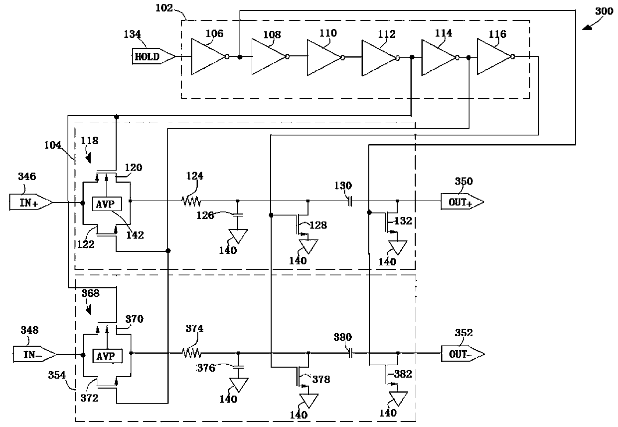
[0031] The circuit and method of the present invention eliminate the harmonic distortion generated by the sample and hold circuit.
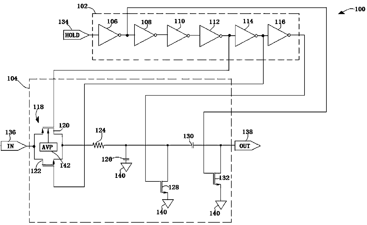
[0032] like figure 1 As shown, a known sample and hold circuit 100. Circuit 100 includes inverter bank 102 to control the timing of circuit 100 in response to a hold signal at hold input 134; main sampling section 104 tracks and holds the voltage at signal input 136 so that it can Measured. Inverter bank 102 is composed of six inverters 106 , 108 , 110 , 112 , 114 and 116 . Main sampling section 104 consists of input diversion switch pair 118 (formed by input diverter switches 120 and 122 ), base resistor 124 , base capacitor 126 , ground diversion switch 128 , sampling capacitor 130 and sampling switch 132 . As shown, switches 120 , 122 , 128 , and 132 are MOSFETs, however, JFETs, bipolar transistors, and other suitable switching devices may be used to implement circuit 100 . Although not shown in the figure 1 In the switch 122 , 128 and 13...
PUM
 Abstract
Description
Claims
Application Information
 - R&D
- Intellectual Property
- Life Sciences
- Materials
- Tech Scout
- Unparalleled Data Quality
- Higher Quality Content
- 60% Fewer Hallucinations
Browse by: Latest US Patents, China's latest patents, Technical Efficacy Thesaurus, Application Domain, Technology Topic, Popular Technical Reports.
© 2025 PatSnap. All rights reserved.Legal|Privacy policy|Modern Slavery Act Transparency Statement|Sitemap|About US| Contact US: help@patsnap.com


