Low profile component tie

a low-profile, component technology, applied in the direction of packaging, transportation and packaging, flexible elements, etc., can solve the problems of increasing the overall bundle diameter, time-consuming process, and inconvenient use, and achieve the effect of low profile, low profile and low profil

Active Publication Date: 2020-07-07
TYCO ELECTRONICS LOGISTICS AG (CH)
View PDF19 Cites 0 Cited by
  • Summary
  • Abstract
  • Description
  • Claims
  • Application Information

AI Technical Summary

Problems solved by technology

However, known cable ties are not without disadvantages.
For example, the retention mechanisms are typically bulky and extend a considerable distance outward from the cable or cable bundle, increasing the overall bundle diameter.
Such process may be time consuming.

Method used


Image

  • Low profile component tie
  • Low profile component tie
  • Low profile component tie

Examples


Embodiment Construction

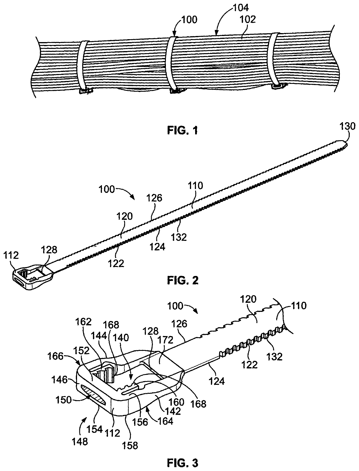
[0026]FIG. 1 illustrates a plurality of low profile component ties 100 formed in accordance with an exemplary embodiment. The component ties 100 are secured to one or more components 102. For example, the component ties 100 wrap around the components 102 and are self-secured to hold or bundle the components 102. In the illustrated embodiment, the components 102 are cables arranged as a cable bundle 104. However, the component ties 100 may be used to secure other types of components in alternative embodiments. The component ties 100 may secure the components 102 together to each other as part of a bundle and / or may secure the component 102 to another device or structure.

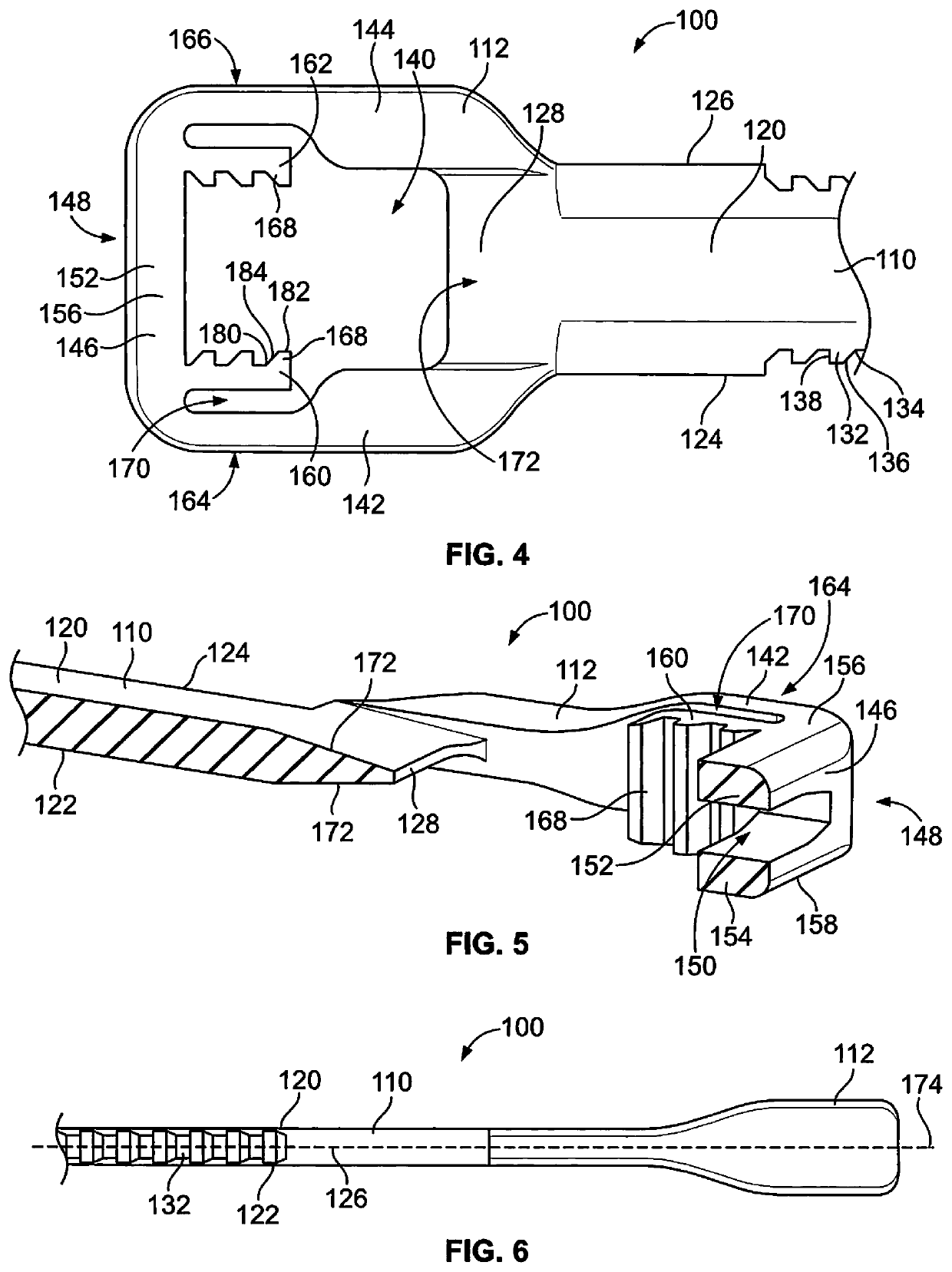
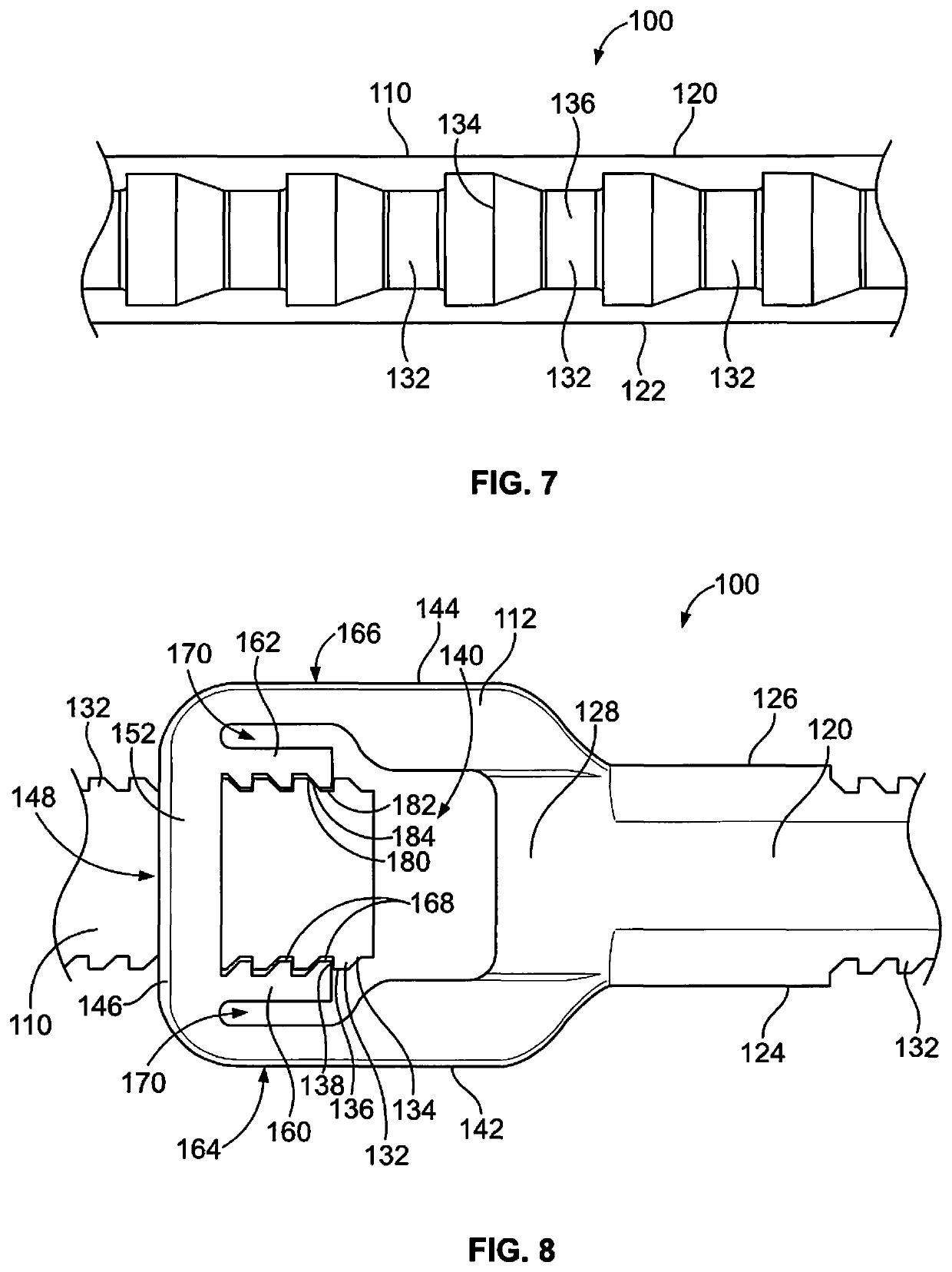
[0027]In an exemplary embodiment, each component tie 100 has a low profile to minimize impact to the overall bundle diameter of the cable bundle 104. The low profile component tie 100 minimizes snag points by being low profile, which may reduce damage to neighboring components or bundles. The low profile component tie...


PUM


Abstract

A low profile component tie includes a strap having a top and a bottom. The strap is configured to wrap around a component with the bottom facing the component. The strap has sides between the top and the bottom. The strap has teeth disposed along at least one of the sides. The strap extends between a root end and a distal end. A head is provided at the root end of the strap. The head has a channel configured to receive the strap. The head has at least one pawl provided in the channel. The pawl engages at least one of the teeth along the side of the strap to secure the strap in the head.

Description

BACKGROUND OF THE INVENTION[0001]The subject matter herein relates generally to a low profile component tie.[0002]Component ties are used to secure and tie one or more components, such as cables. Such cable ties may tie the cables together in a bundle and / or tie the cables to another structure. Cable ties typically include a retention mechanism and a strap that is secured around the components to the retention mechanism.[0003]However, known cable ties are not without disadvantages. For example, the retention mechanisms are typically bulky and extend a considerable distance outward from the cable or cable bundle, increasing the overall bundle diameter. The retention mechanisms are typically block shaped and define snag points for the cable bundle. For example, when the cable bundle is routed through a structure or chassis, such as within a building, machine, vehicle or aircraft, the block shaped retention mechanism may snag or catch on a portion of the structure or on another cable t...

Claims


Application Information

Patent Timeline
Patent Type & Authority Patents(United States)
IPC IPC(8): B65D63/10
CPCB65D63/1063B65D63/1081B65D63/1072
Inventor SWATKO, NICHOLAS JOHNRATZLAFF, THOMAS D.
Owner TYCO ELECTRONICS LOGISTICS AG (CH)
Why Eureka
Try Eureka