
Surgical device and methods of use

a surgical device and a technology of a surgical device, applied in the field of surgical devices and methods of use, can solve the problems of affecting the accuracy of the root apex location of the actual surgery, affecting the accuracy of the surgical procedure, so as to achieve accurate and accurate mapping of the desired structure, accurate identification of the location, and small field of view

Active Publication Date: 2022-07-26
TEXAS A&M UNIVERSITY
View PDF6 Cites 0 Cited by
  • Summary
  • Abstract
  • Description
  • Claims
  • Application Information

AI Technical Summary

Benefits of technology

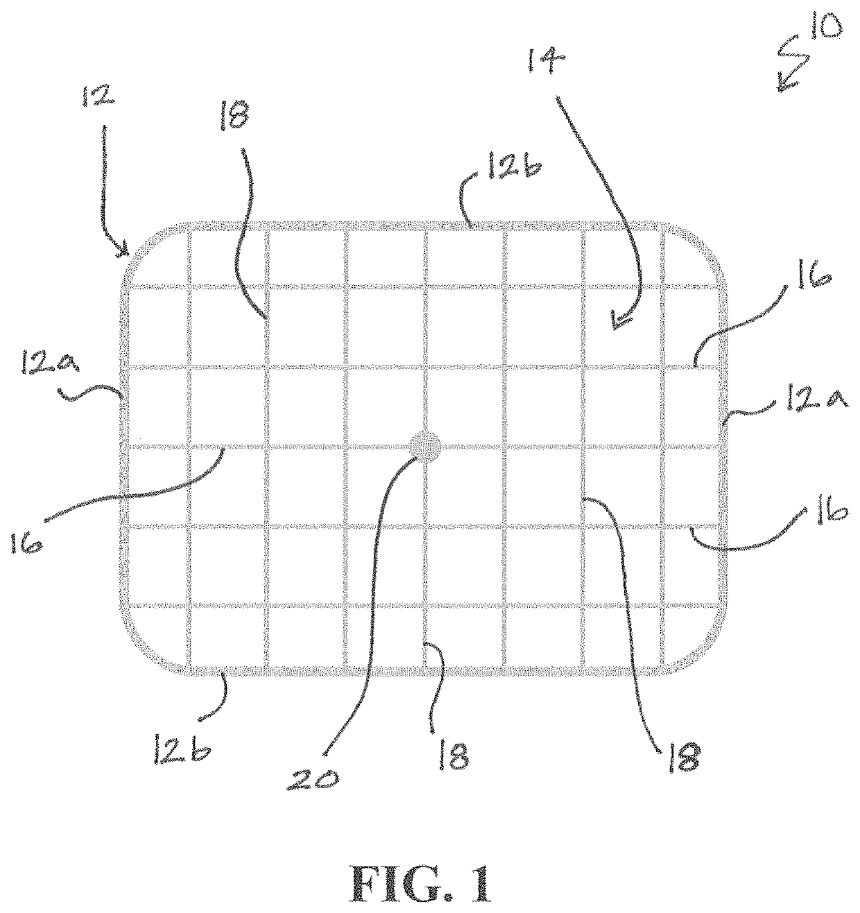
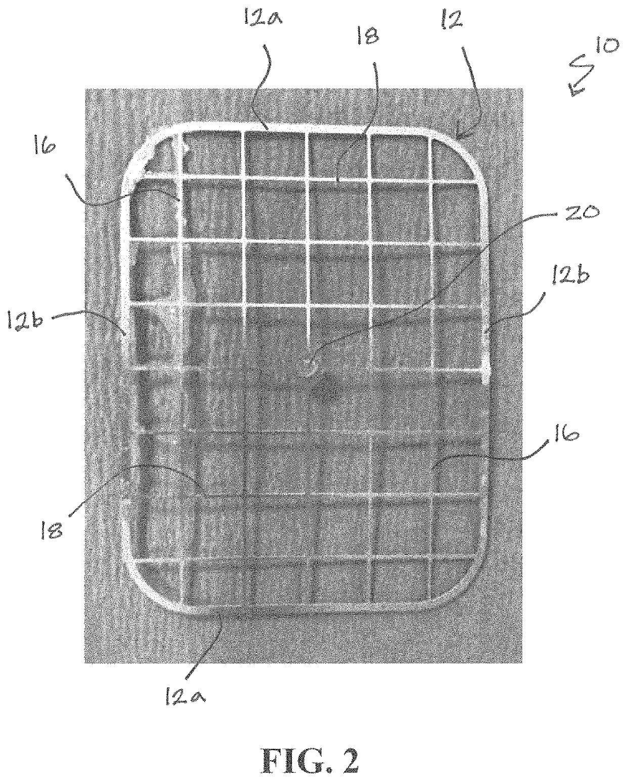
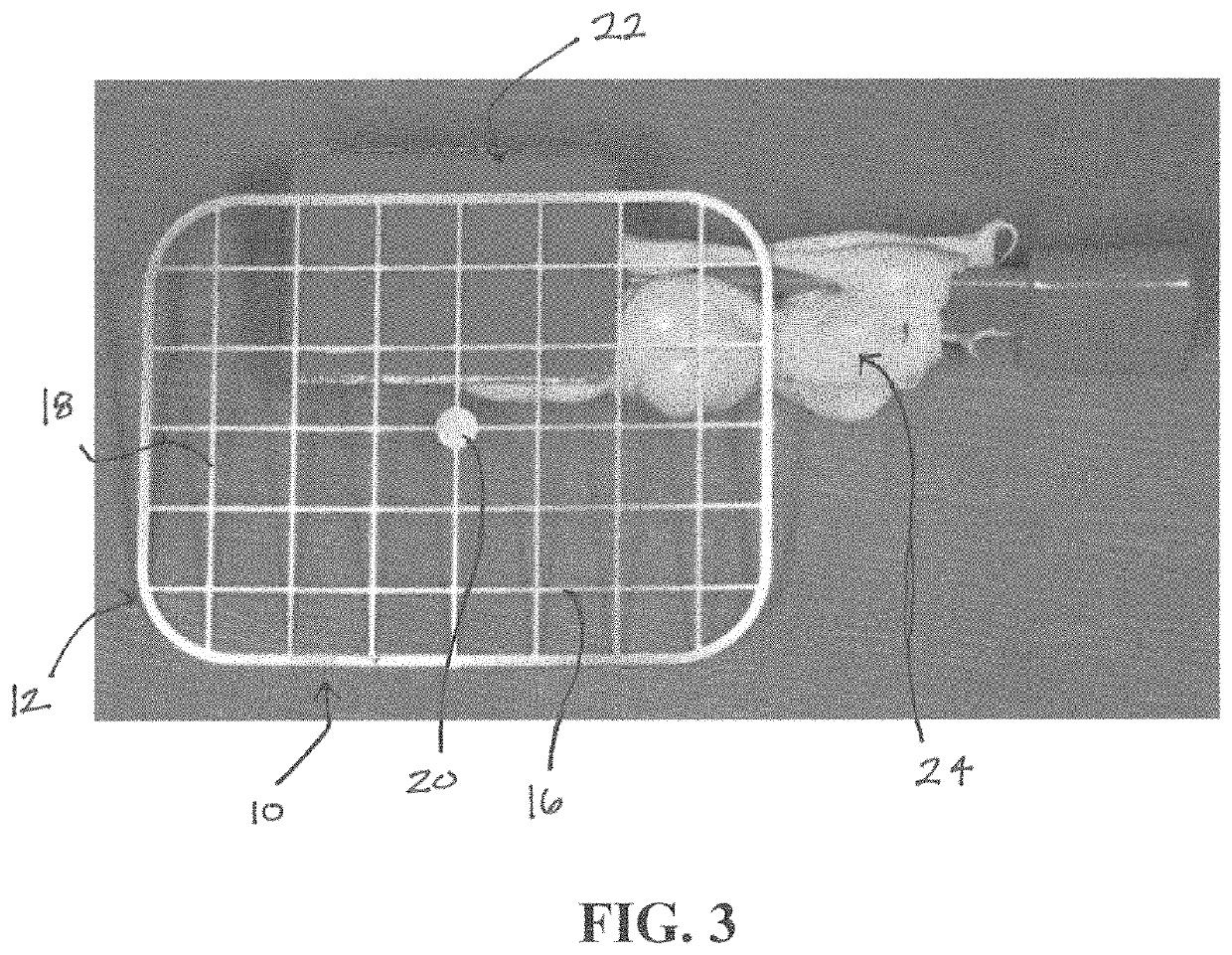
[0005]The present invention relates generally to a device configured for assisting professionals, and particularly craniofacial and dental surgical professionals and endodontists, in accurately identifying the location of a desired surgical site by Cone Beam Computed Tomography (CBCT). CBCT is a CT scan with a very small field of view. CBCT may therefore be used according to the present invention together with the described techniques and tools by the dental or other surgical professional to precisely map the root tip (or apex) of a patient's tooth, and this information may then be transferred to the herein described device. The device may thus be utilized in this manner to precisely remove the located structure, such as a root tip (apex) or other structure. The device can be used to easily and accurately map the desired structure, such as the root apex location information identified on a CBCT scan image, and transfer that information to the surgical device during the surgical procedure.
[0011]In some embodiments, a method for using the device as a dental surgical assistance device is provided. For example, the device is used while performing endodontic surgery in order to assist a dental professional in accurately identifying the precise location of the root apex for the tooth to be operated on during the surgical procedure. According to one embodiment, the method can comprise the steps of: providing a grid-pattern guide device adjacent to an identified tooth and capturing a cone beam computed tomography scan image of the grid-pattern guide device and the identified tooth, wherein the grid-pattern guide device comprises a grid structure having a plurality of intermediate cross bars; identifying a guide position on the grid-pattern guide device by determining a pre-planned drilling location on the cone beam computed tomography scan image corresponding to a position on the identified tooth where the root apex is located and selecting a location on the grid-pattern guide device that corresponds to the pre-planned drilling location; and using the grid-pattern guide device during the endodontic surgical procedure by locating the guide position on the grid-pattern guide device and drilling the individual tooth at a drill location associated with the guide position to expose the root apex of the patient's tooth.

Problems solved by technology

One of the challenges of this procedure is identifying the exact location of the tip (or apex) of the root.
Many times, in an attempt to find the apex of the root, the dental professional may remove an unnecessary amount of bone during the osteotomy procedure.
Not only is this an undesirable result for the tooth, it also may risk damage to the vital structures near the root (e.g., nerve, sinus).
However, while the CBCT scan allows the dental professional to identify the location of the root apex, it is difficult for dental professionals to use the CBCT scan results to accurately locate the root apex during actual surgery.
This is, at least in part, because it is difficult to transfer the information gained from the CBCT scan (which has a very small field of view) to a real patient during surgery.
However, this solution is not efficient or effective because it requires the use of both a digital impression device and a 3-D printer, which are not common among endodontists and other dental professionals, are expensive, and are time consuming to use.

Method used


Image

  • Surgical device and methods of use
  • Surgical device and methods of use
  • Surgical device and methods of use

Examples


Embodiment Construction

[0022]The invention will now be described with reference to the drawing figures, in which like reference numerals refer to like parts throughout. For purposes of clarity in illustrating the characteristics of the present invention, proportional relationships of the elements have not necessarily been maintained in the drawing figures.

[0023]The following detailed description of the invention references specific embodiments in which the invention can be practiced. The embodiments are intended to describe aspects of the invention in sufficient detail to enable those skilled in the art to practice the invention. Other embodiments can be utilized and changes can be made without departing from the scope of the present invention. The present invention is defined by the appended claims and the description is, therefore, not to be taken in a limiting sense and shall not limit the scope of equivalents to which such claims are entitled.

[0024]Turning to the several figures, the present invention...


PUM


Abstract

A surgical device for identification of a surgical site of interest, such as a craniofacial or dental site (root apex of an identified tooth), and a method for using the device is provided. The device includes a perimeter bar and a plurality of intermediate cross bars arranged in a grid structure. The device can be used during a surgical procedure requiring enhanced precision, such as during an endodontic surgical procedure, by positioning the device next to a patient's tooth and capturing a CBCT image, the CBCT image being used to identify a drilling location. The device can be repositioned alongside the patient's tooth, and used to identify an accurate drilling position.

Description

BACKGROUND OF THE INVENTION[0001]Dental professionals often use endodontic surgery (apicoectomy) as a surgical treatment option for a damaged, injured, or infected tooth, particularly when root canal treatment is unsuccessful. In this procedure, the gum tissue near the tooth is opened to see the underlying bone and to remove any inflamed or infected tissue. The very end of the root is also removed. One of the challenges of this procedure is identifying the exact location of the tip (or apex) of the root. In order to locate the root apex, an osteotomy is often performed on the affected tooth to remove the bone covering the apex of the root and to make a small window to the apex. Many times, in an attempt to find the apex of the root, the dental professional may remove an unnecessary amount of bone during the osteotomy procedure. Not only is this an undesirable result for the tooth, it also may risk damage to the vital structures near the root (e.g., nerve, sinus). According to the Am...

Claims


Application Information

Patent Timeline
Patent Type & Authority Patents(United States)
IPC IPC(8): A61C19/04A61B6/00A61B90/00A61C5/40A61B6/14A61B6/03
CPCA61C19/042A61B6/032A61B6/145A61B6/4085A61B90/39A61C5/40A61B2090/3966A61B2090/3762A61C1/082A61B6/14A61B6/12
Inventor JALALI, SID POORYAKRUPNICK, DAVID
Owner TEXAS A&M UNIVERSITY
Learn More