System for construction of composite U shaped reinforced girders bridge deck and methods thereof

a technology of reinforced concrete and composite girders, which is applied in the direction of bridges, bridge structural details, bridge erection/assembly, etc., can solve the problems of increasing construction time, affecting the construction efficiency of bridges, so as to reduce the moment and deflection, increase the moment of inertia, and save construction costs

Active Publication Date: 2020-07-07
THAVAMANI PANDI VELLAISAMY +1
View PDF27 Cites 2 Cited by
  • Summary
  • Abstract
  • Description
  • Claims
  • Application Information

AI Technical Summary

Benefits of technology

[0012]3. It is yet another object of the present invention to provide, cross girders which is placed at 5 cm above bottom flange of main girder, and end girders which are placed over the bottom flange of main girder and connected to both web and flange of main girder for better transfer of loads to bearing.
[0015]6. It is another object of the present invention to provide a new force transfer system with composite interaction of U shaped RCC girder and main girders resulting in substantial reduction of deflection and moments at centre of span in main girders making it suitable for longer span.
[0016]7. It is yet another object of the present invention to provide U shaped RCC girder whose frame action results in substantial reduction of moments and deflection in cross girders.
[0020]Moreover, the top flange of said main girder is unsymmetrical to thereby take said U shaped RCC girder over said top flange. The top flange of said main girder is projected inside a concrete by 3 cm for welding. The properties of main girder, cross girders and U girder are modified to increase moment of inertia. The stiffeners are provided on outer face of the main girders. The top flange of cross girders is bent to provide camber in a carriage way which is used upto four lanes for highway and upto three lanes for railway / metro track. The frame action of the system reduces the moment and deflections in both main and cross girders. To economize construction of main and cross girders, pre camber is provided to counteract dead load and 50% of live load deflections. The semi through steel composite girder arrangement is possible to provide spans up to 36 m with plate girder E250 / 350 grade and Span 45 m above with E410 grade. For spans 45 and above, pre camber is to be provided to contain deflection less than L / 600. Light weight concrete of density 1600 kg / m3 made of Expanded Shale Clay and Slate can be used to economies the construction cost in adopting the same section for longer spans.

Problems solved by technology

Bracing and diaphragm arrangements add to weight and increase construction time.
The crossing needs to be closed interfering traffic, which is not suitable for fast track construction.
Ladder deck system steel usage is less but depth of construction is more, which leads to increase in the approach cost.
More area exposed makes it vulnerable for rain and weathering agents.
The casting is done at site needing elaborate form work, which is constructed for short spans up to 18 m and also not suitable for multi lane Road / Railway bridges.
The top flange width of concrete is unequal and composite properties of the main girders are not fully used.
The existing traffic is obstructed due to abutments supporting main girders and elaborate formwork arrangement.
From the above description, it is understood that the previous construction methods were being observed, which is not suitable for multilane road / rail and traffic obstructed.

Method used


Image

  • System for construction of composite U shaped reinforced girders bridge deck and methods thereof
  • System for construction of composite U shaped reinforced girders bridge deck and methods thereof
  • System for construction of composite U shaped reinforced girders bridge deck and methods thereof

Examples


Embodiment Construction

[0030]The preferred embodiment of the present invention will now be explained with reference to the accompanying drawings. It should be understood however that the disclosed embodiments are merely exemplary of the invention, which may be embodied in various forms. The following description and drawings are not to be construed as limiting the invention and numerous specific details are described to provide a thorough understanding of the present invention, as the basis for the claims and as a basis for teaching one skilled in the art how to make and / or use the invention. However in certain instances, well-known or conventional details are not described in order not to unnecessary obscure the present invention in detail.

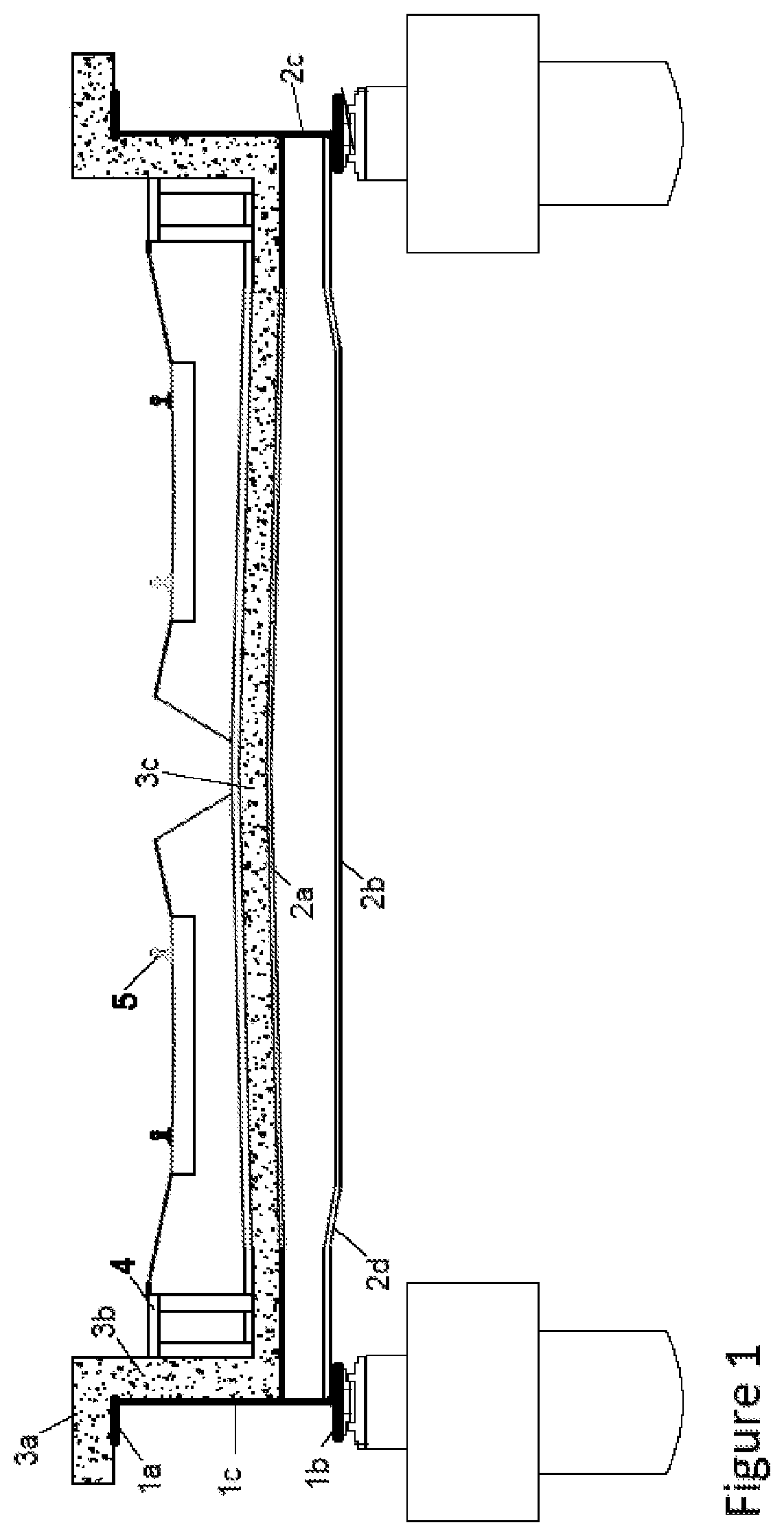
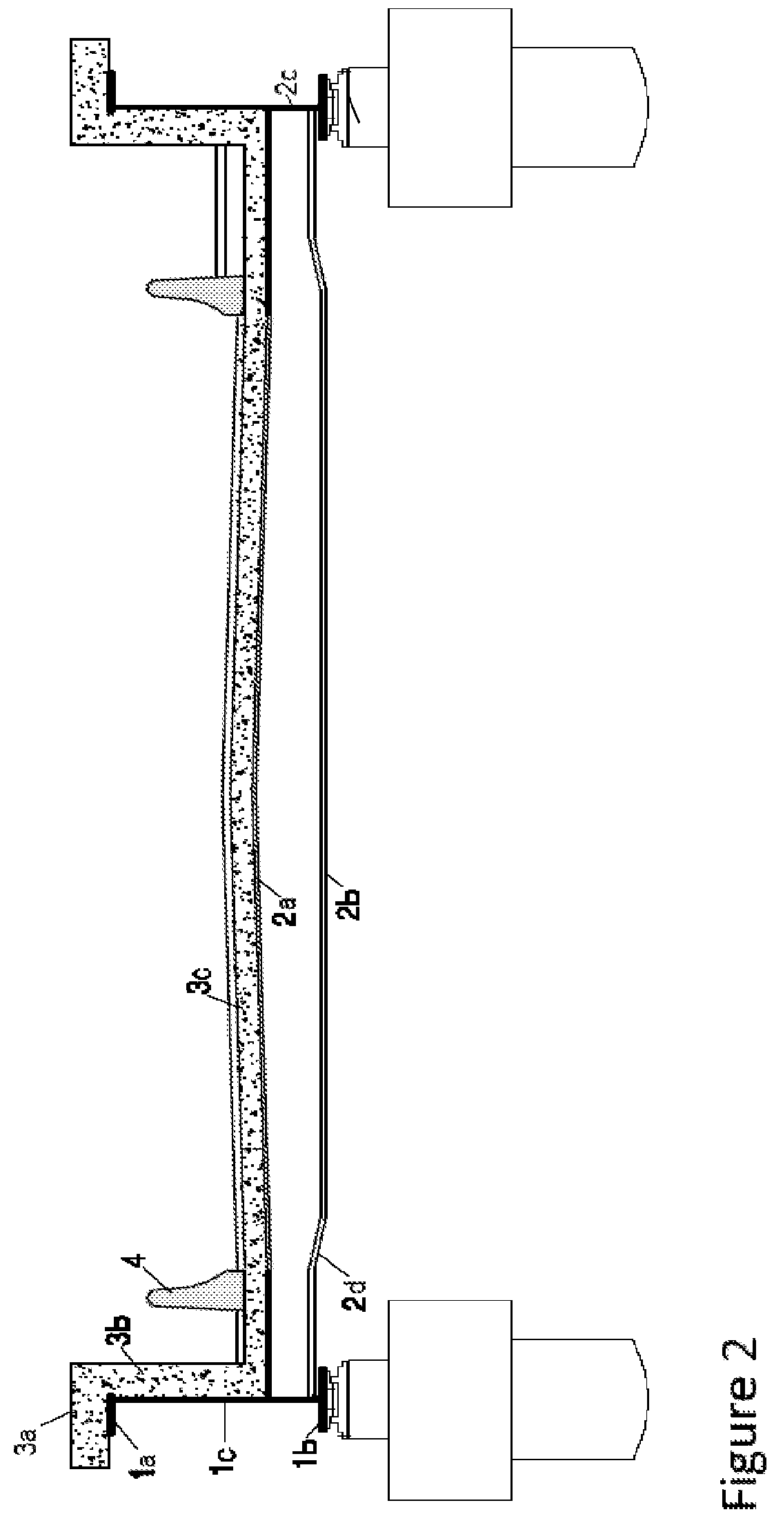
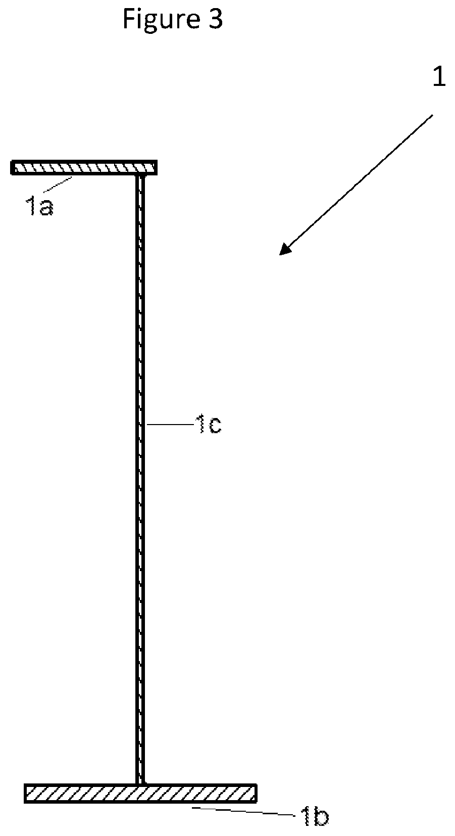
[0031]With reference to the FIG. 1, the invention is illustrated as applied to, the schematic representation of system of construction of composite U shaped reinforced concrete and steel girders bridge deck implemented in a railway bridge, comprising a plurality of mai...


PUM


Abstract

A composite bridge deck including U shaped reinforced concrete and steel girders, and construction methods thereof. The bridge deck consists of a plurality of steel main girders with unsymmetrical top flange, the plurality of cross girders being connected above bottom flange of main girders and U shaped RCC girder comprising of concrete flange above main girder, web and deck slab above cross girder. Inspection path / crash barrier provided for Rail / Road. This bridge deck is adoptable up to 3 Tracks / four lane Roads. In Cast in situ construction, main girders are placed over supports. Cross girders are connected and concreted. In precast construction, main girder with top slab is precast and placed over supports. Two or more cross girders with precast slab are connected to web of main girder. Concrete web portion is cast in situ.

Description

FIELD OF THE INVENTION[0001]The present invention relates to the field of bridge engineering in particular to steel concrete composite bridge deck for economical and fast track construction. More particularly, the present invention relates to the system and method of construction of composite U shaped reinforced concrete and steel girders bridge deck for use in Railway, Metro and Highway bridges.BACKGROUND OF THE INVENTION[0002]In composite construction of Road bridges, the main girders are placed along traffic direction at spacing of around 2.5 m to cover the deck width. Each girder is designed to take live loads passing in that alignment. Construction depth plays an important role in the design of the bridge and cost of approach. The depth of construction (top of road level to bottom of girder) is 2 m to 3.5 m for spans of 24 m to 45 m. Half through steel girders are constructed and it can be adopted for shorter spans due to its lesser moment of inertia.[0003]In multi girder syste...

Claims


Application Information

Patent Timeline
Patent Type & Authority Patents(United States)
IPC IPC(8): E01D19/12E04C3/294E01D2/00
CPCE01D19/12E04C3/294E01D2/00E01D2101/268E01D19/125E01D21/00
Inventor THAVAMANI PANDI, VELLAISAMYJEYANTHI RANI, THAVAMANI PANDI
Owner THAVAMANI PANDI VELLAISAMY
Why Eureka
Try Eureka