Image re-projection for foveated rendering

a technology of foveated rendering and image, applied in the direction of instruments, static indicating devices, optical elements, etc., can solve the problems of limited processing power and memory capacity of graphics processing devices performing rendering, difficult rendering of scene, especially real-time rendering, etc., to improve the position of an image to be displayed, and improve the position of an imag

Active Publication Date: 2020-07-14
TOBII TECH AB
View PDF3 Cites 8 Cited by
  • Summary
  • Abstract
  • Description
  • Claims
  • Application Information

AI Technical Summary

Benefits of technology

[0004]In some embodiments, a method for improving the position of an image to be displayed is provided. The method may include receiving a first estimation of a predicted gaze point of a user on a display device at the time when the image will be displayed. The first estimation of the predicted gaze point is determined before the start of rendering a portion of the image related to the first estimation of the predicted gaze point. The method may further include causing the image, including the portion of the image, to be rendered based on the first estimation of the predicted gaze point. The method may also include receiving a second estimation of the predicted gaze point at the time when the image will be displayed. The second estimation of the predicted gaze point is determined after rendering of the portion of the image has started. The method may further include in response to determining that the second estimation of the predicted gaze point is different from the first estimation of the predicted gaze point, adjusting the rendered image based on the second estimation of the predicted gaze point and transmitting the adjusted rendered image to the display device for display.
[0005]In another embodiment, a computing system for improving the position of an image to be displayed is provided. The computing system may include a non-transitory computer-readable medium storing program code of an image processing application, and a processing device communicatively coupled to the non-transitory computer-readable medium. The processing device may be configured to execute the program code and perform operations that include receiving a first estimation of a predicted gaze point of a user on a display device at the time when the image will be displayed. The first estimation of the predicted gaze point is determined before the start of rendering a portion of the image related to the first estimation of the predicted gaze point. The operations may further include causing the image, including the portion of the image, to be rendered based on the first estimation of the predicted gaze point. The operations may further include receiving a second estimation of the predicted gaze point at the time when the image will be displayed. The second estimation of the predicted gaze point is determined after rendering of the portion of the image has started. The operations may further include, responsive to determining that the second estimation of the predicted gaze point is different from the first estimation of the predicted gaze point, adjusting the rendered image based on the second estimation of the predicted gaze point and transmitting the adjusted rendered image to the display device for display.
[0006]In another embodiment, a non-transitory machine readable medium having instructions thereon for improving the position of an image to be displayed is provided. The instructions may be executable by one or more processors to perform operations that may include receiving a first estimation of a predicted gaze point of a user on a display device at the time when the image will be displayed. The first estimation of the predicted gaze point is determined before the start of rendering a portion of the image related to the first estimation of the predicted gaze point. The operations may further include causing the image, including the portion of the image, to be rendered based on the first estimation of the predicted gaze point. The operations may further include receiving a second estimation of the predicted gaze point at the time when the image will be displayed. The second estimation of the predicted gaze point is determined after rendering of the portion of the image has started. The operations may further include responsive to determining that the second estimation of the predicted gaze point is different from the first estimation of the predicted gaze point, adjusting the rendered image based on the second estimation of the predicted gaze point and transmitting the adjusted rendered image to the display device for display.

Problems solved by technology

Rendering is a computationally expensive process in which the entire scene's spatial, textural, and lighting information are combined to determine the color value of each pixel in the rendered image.
Graphics processing devices performing the rendering, however, have limited processing power and memory capacity.
These limits make the rendering of the scene, especially real-time rendering, a challenging task.
However, the high-quality area of the rendered image displayed to a user does not always match the foveated region of the user.
Reasons for this mismatch include the latency introduced by the rendering process, and the latency and inaccuracy in the gaze point estimation, especially in scenarios where saccade or blinking has occurred.
Consequently, the content that is projected to the user's foveated region at the time of display may be rendered in low quality causing unpleasant experience to the user.

Method used


Image

  • Image re-projection for foveated rendering
  • Image re-projection for foveated rendering
  • Image re-projection for foveated rendering

Examples


Embodiment Construction

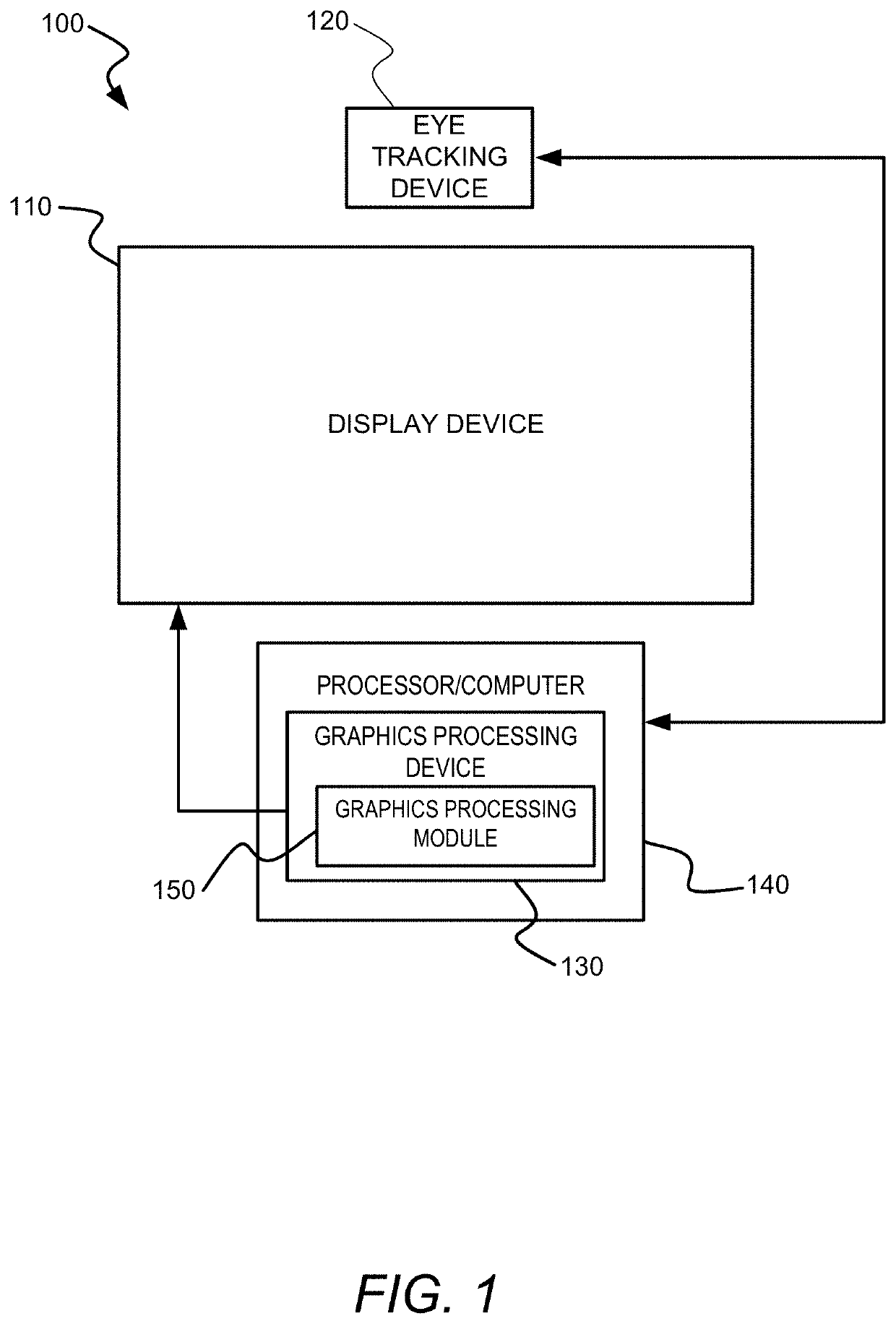
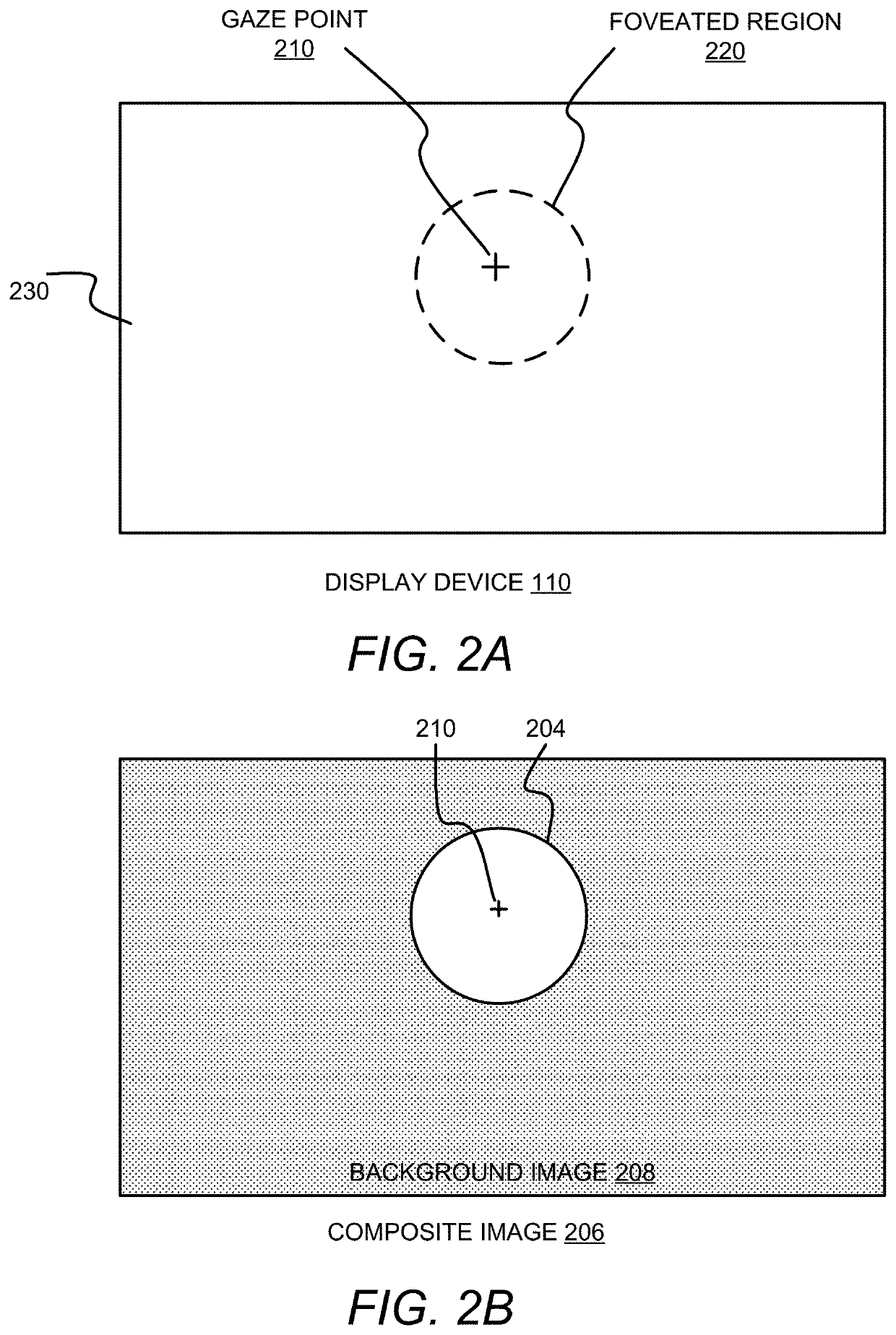
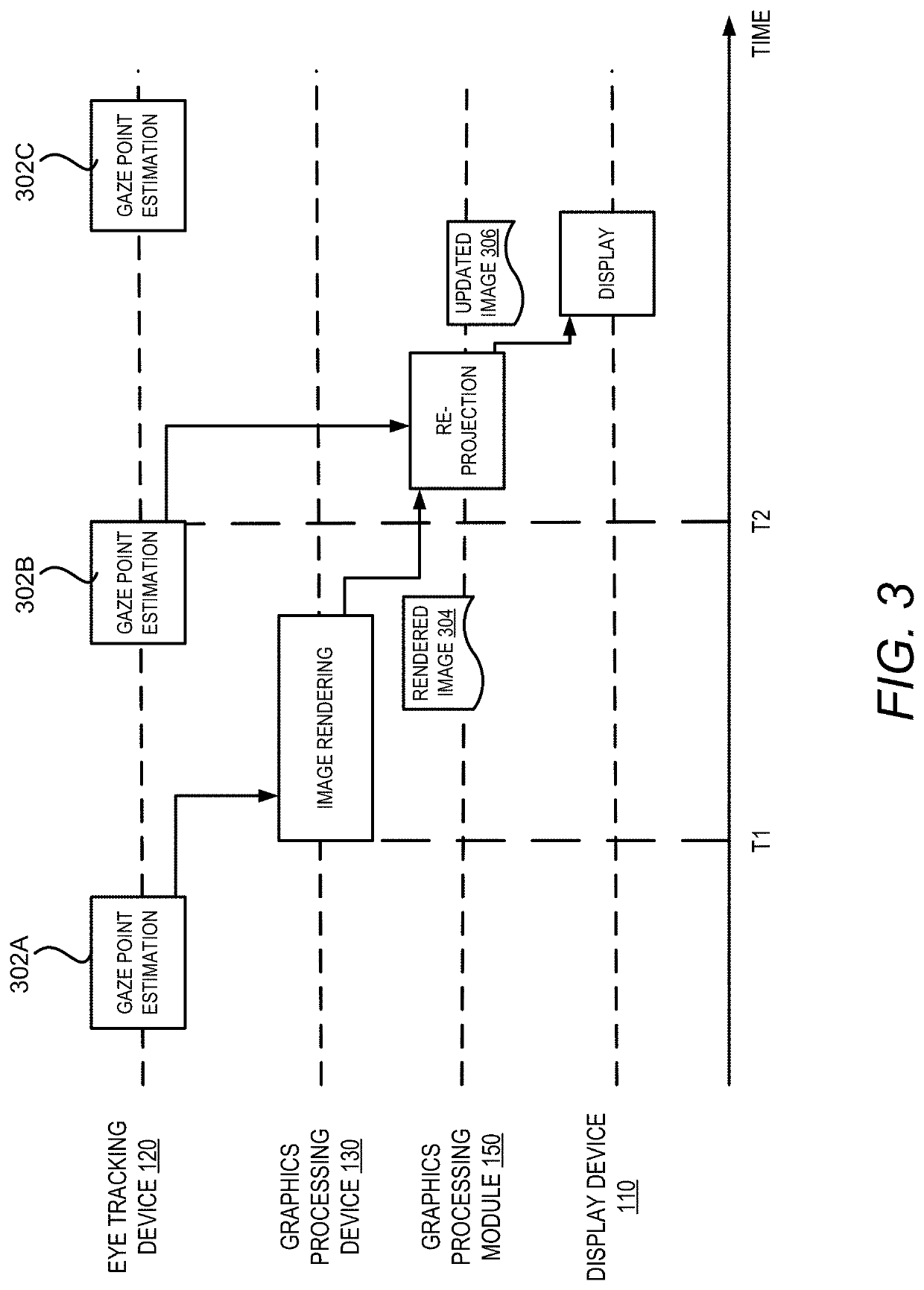
[0016]Embodiments for improving foveated rendering through image re-projection are disclosed. In an example, a graphics processing device receives a first estimation of a predicted gaze point of a user on a display device. Based on the first estimation of the predicted gaze point, the graphics processing device implements or cause to be implemented foveated rendering by generating a high-quality portion of the image corresponding to a foveated region containing the first estimation of the predicted gaze point of the user, and the remaining part of the image for the non-foveated region. The estimation of the predicted gaze point of the user is determined before the start of rendering the high-quality portion of the image. After rendering the high-quality portion of the image has started, the graphics processing device receives a second estimation of the predicted gaze point of the user. The graphics processing device determines if the second estimation of the predicted gaze point of ...


PUM


Abstract

Technologies for improving foveated rendering of an image by improving the position of the image to be displayed through image re-projection are disclosed. For example, a method may include receiving a first estimation of a predicted gaze point of a user on a display device that is determined before starting rendering a high-quality portion of the image. The method may further include causing the image to be rendered based on the first estimation of the predicted gaze point. The method may also include receiving a second estimation of the predicted gaze point. The second estimation of the predicted gaze point is determined after rendering of the high-quality portion of the image has started. Responsive to determining that the second estimation of the predicted gaze point is different from the first estimation, the method may include adjusting the rendered image based on the second estimation of the predicted gaze point and transmitting the adjusted image to the display device for display.

Description

BACKGROUND[0001]Rendering and displaying a computer-generated scene on a display has increased in importance in areas such as gaming, modeling, and movies. Rendering is a computationally expensive process in which the entire scene's spatial, textural, and lighting information are combined to determine the color value of each pixel in the rendered image. Graphics processing devices performing the rendering, however, have limited processing power and memory capacity. These limits make the rendering of the scene, especially real-time rendering, a challenging task.[0002]To speed up the rendering process, foveated rendering is sometimes employed. Foveated rendering uses an eye tracker to reduce the rendering workload based on the observation that human vision typically focuses on the portion of the screen near the gaze point whereas the visual acuity drops dramatically in the peripheral vision (i.e. the area outside of the zone gazed by the fovea). In foveated rendering, the content in a...

Claims


Application Information

Patent Timeline
Patent Type & Authority Patents(United States)
IPC IPC(8): G06F3/01G09G5/37
CPCG06F3/013G09G5/37G09G2320/066G09G2354/00G09G2340/0407G06T15/10G06T3/005G09G5/391G09G2320/0686G09G2320/0252G02B2027/0187G02B27/0093G02B27/017G02B2027/0138G02B2027/014
Inventor RÖNNGREN, DENNY ALEXANDER
Owner TOBII TECH AB
Why Eureka
Try Eureka