Depth imaging system and method for controlling depth imaging system thereof

a depth imaging and depth imaging technology, applied in the field of visual imaging, can solve the problems of inaccurate depth information and poorly defined intersection points, and achieve the effect of accurate depth information

Active Publication Date: 2020-07-14
ULSEE
View PDF3 Cites 3 Cited by
  • Summary
  • Abstract
  • Description
  • Claims
  • Application Information

AI Technical Summary

Benefits of technology

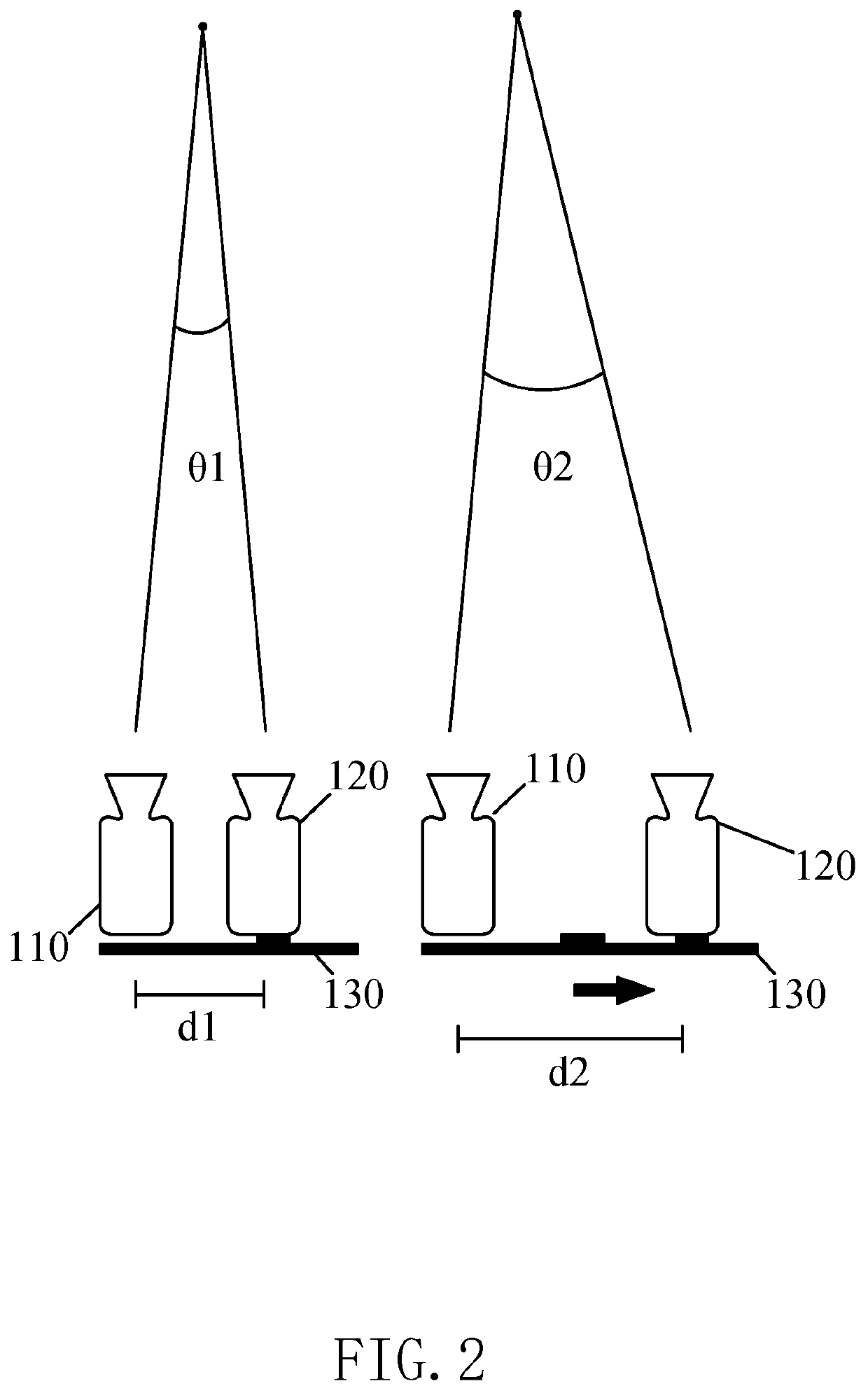
[0022]With the above technical solution, the beneficial effects of the depth imaging system of the present invention are as follows: an optimal baseline can be adjusted to obtain accurate depth information.

Problems solved by technology

However, if the two 3D lines are too close to be almost parallel, the intersection point is poorly defined.
Hence, how to accurately obtain depth information is an important issue in this field.

Method used


Image

  • Depth imaging system and method for controlling depth imaging system thereof
  • Depth imaging system and method for controlling depth imaging system thereof
  • Depth imaging system and method for controlling depth imaging system thereof

Examples


Embodiment Construction

[0039]The following disclosure provides many different embodiments, or examples, for implementing different features of the provided subject matter. Specific examples of components and arrangements are described below to simplify the present disclosure. These are, of course, merely examples and are not intended to be limiting. For example, the formation of a first feature over or on a second feature in the description that follows may include embodiments in which the first and second features are formed in direct contact, and may also include embodiments in which additional features may be formed between the first and second features, such that the first and second features may not be in direct contact. In addition, the present disclosure may repeat reference numerals and / or letters in the various examples. This repetition is for the purpose of simplicity and clarity and does not in itself dictate a relationship between the various embodiments and / or configurations discussed.

[0040]F...


PUM


Abstract

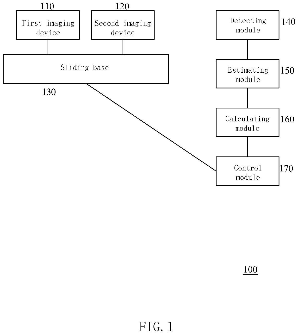
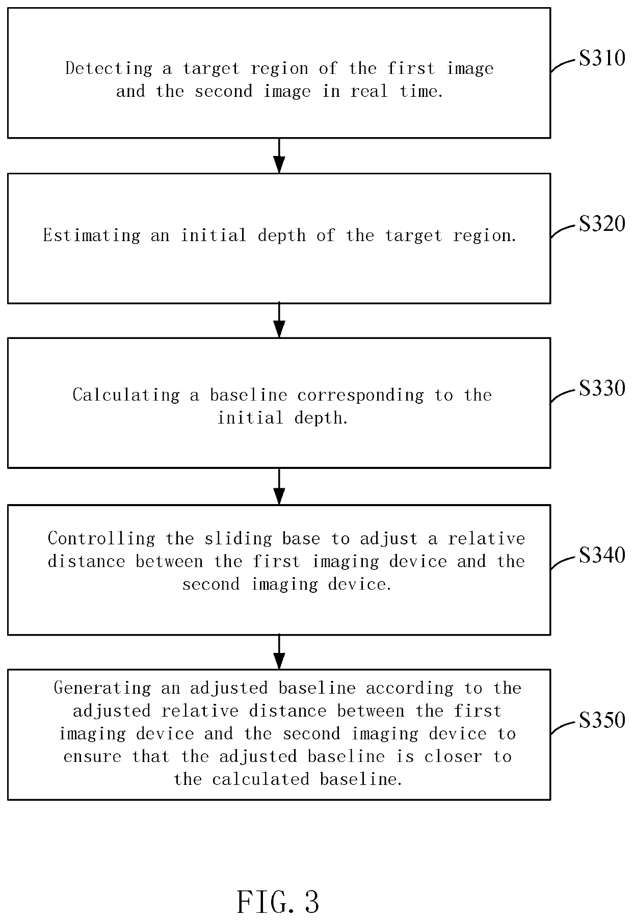
A depth imaging system and a control method thereof are provided. The depth imaging system includes a first imaging device, a second imaging device, a sliding base, a detecting module, an estimating module, a calculating module, and a control module. The first imaging device and the second imaging device are mounted on the sliding base. The detecting module detects a target region of the first image and the second image. The estimating module estimates an initial depth of the target region. The calculating module calculates a baseline corresponding to the initial depth. The control module controls the sliding base to adjust a relative distance between the first imaging device and the second imaging device. The calculating module generates an adjusted baseline according to the adjusted relative distance between the first imaging device and the second imaging device, such that the adjusted baseline is closer to the calculated baseline.

Description

FIELD OF THE DISCLOSURE[0001]The present invention relates to an imaging visual field, and more particularly to, a depth imaging system having two imaging devices that can move apart or closer and a method for controlling a depth imaging system thereof.BACKGROUND OF THE INVENTION[0002]In surveillance for facial recognition, 3D information can be used to reliably identify a human face from facial feature data. In addition, 3D depth information can help in monitoring and image understanding.[0003]One known method of capturing 3D depth information is using depth cameras—image features are matched between a pair of views taken a distance apart (“baseline”). Conventionally, a baseline defines a region of reliable 3D space where depth information is reliable. In order to “triangulate” a 3D point, two views of the 3D point are identified, and the 3D point is calculated by back-projecting and intersecting two rays (3D lines) from each camera. However, if the two 3D lines are too close to be...

Claims


Application Information

Patent Timeline
Patent Type & Authority Patents(United States)
IPC IPC(8): H04N7/18H04N5/247H04N5/232H04N13/204H04N13/00
CPCH04N5/247H04N13/204H04N5/23296H04N2013/0081H04N2213/001H04N23/959H04N23/67H04N23/695H04N23/90H04N13/239H04N13/296H04N23/69
Inventor BAUMBERG, ADAMMIDDLEBROOK, MARK
Owner ULSEE
Why Eureka
Try Eureka