

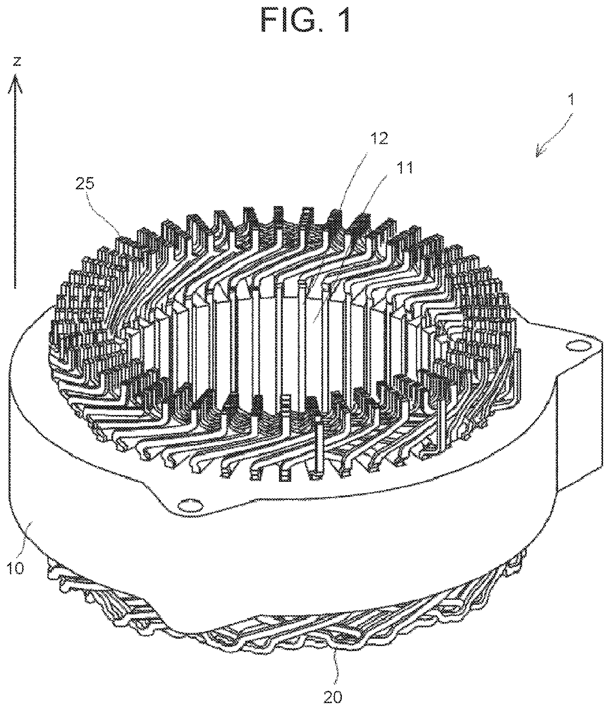
Laser welding method for flat wires
a flat wire, laser welding technology, applied in welding/soldering/cutting articles, manufacturing tools, and capacitors, etc., can solve the problems of laser beam lb passing through and damage to the insulating film of other flat wires, and achieve the effect of avoiding the effects of laser beam entering
- Summary
- Abstract
- Description
- Claims
- Application Information
AI Technical Summary
Benefits of technology
Problems solved by technology
Method used
Image

Examples
first embodiment
Modified Example of First Embodiment
[0060]A modified example of the first embodiment will be described with reference to FIG. 8. FIG. 8 is a side view showing a modified example of the joint part 25 of the first and second flat wires 20a, 20b in the laser welding method for flat wires according to the first embodiment. The right-handed xyz-coordinates shown in FIG. 8 coincide with those in FIG. 2 to FIG. 5.
[0061]In the example shown in FIG. 1, the joint part 25 stands vertically (in the z-axis direction) as indicated by the two-dot dashed line in FIG. 8. In this modified example, this part indicated by the two-dot dashed line is omitted. Specifically, an angle θ that the first end surface 24a of the first flat wire 20a forms with an extension line of an outer surface is smaller than 90°, so that a leading end of the first flat wire 20a has a pointed shape. In addition, the first end surface 24a and the outer surface are connected to each other by an arc-shaped curved surface. Accord...
second embodiment
[0068]Next, a laser welding method for flat wires according to this embodiment will be described with reference to FIG. 12 to FIG. 14. FIG. 12 to FIG. 14 are plan views showing the laser welding method for flat wires according to the second embodiment. The right-handed xyz-coordinates shown in FIG. 12 to FIG. 14 coincide with those in FIG. 2 to FIG. 5.
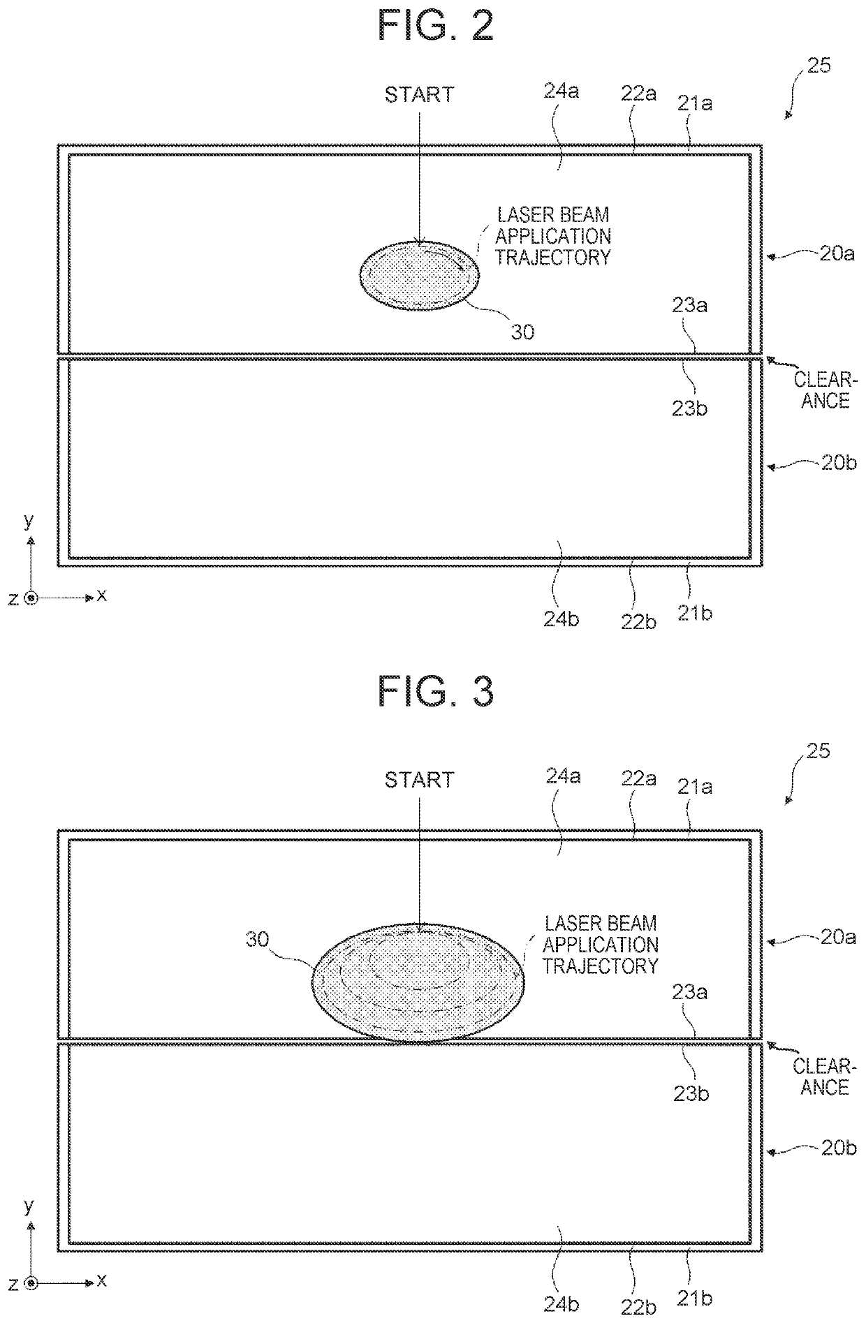
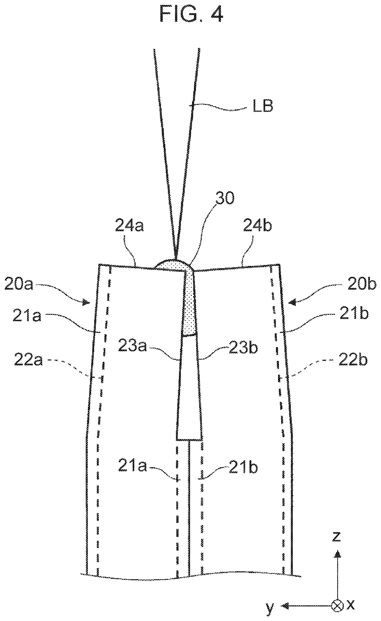
[0069]First, as shown in FIG. 12, the first side surface 23a of the first flat wire 20a that is stripped of the first insulating film 21a and the second side surface 23b of the second flat wire 20b that is stripped of the second insulating film 21b are butted together at the joint part 25. Then, a laser beam is applied in a loop shape inside the first end surface 24a of the first flat wire 20a to form a first molten pool 30a. At the same time, a laser beam is applied in a loop shape inside the second end surface 24b of the second flat wire 20b to form a second molten pool 30b. It is possible to apply a laser beam to the first and secon...
PUM
| Property | Measurement | Unit |
|---|---|---|
| diameter | aaaaa | aaaaa |
| wavelength | aaaaa | aaaaa |
| angle | aaaaa | aaaaa |
Abstract
Description
Claims
Application Information