
Systems and methods for manufacturing of microstructures

a microstructure and manufacturing system technology, applied in the field of microstructures, to achieve the effects of precise complex shapes, high strength to weight ratio, and high stability

Active Publication Date: 2020-07-28
TECHNION RES & DEV FOUND LTD
View PDF11 Cites 3 Cited by
  • Summary
  • Abstract
  • Description
  • Claims
  • Application Information

AI Technical Summary

Benefits of technology

[0010]At least some of the systems, methods, apparatus, and / or code instructions described herein relate to an improved process for generating models of microstructures for analysis, simulation, and / or evaluation. For example, the improved models of the microstructures may be used to simulate, analyze, evaluate and / or improve: rigidity, stability, high strength to weight, a hierarchical structure, uniformly sized tiles, precise complex shapes, and / or smooth and / or continuous surfaces.
[0011]At least some of the systems, methods, apparatus, and / or code instructions described herein relate to an improved process for manufacturing microstructures, optionally by an additive manufacturing device and / or other manufacturing devices described herein. For example, the improved manufactured microstructures have an improved optimized internal structure of the material, for example, improved rigidity, stability, high strength to weight ratio, a hierarchical structure, uniformly sized tiles, precise complex shapes, and / or smooth and / or continuous surfaces. For example, the created microstructure of the object is porous, resulting in relatively low weight in comparison to a non-porous object, while having high strength.
[0027]In a further implementation form of the first, second, and third aspects, at least one surface of each of the plurality of instances of the freeform tile coincides and is connected with at least one other surface of another of at least one of the plurality of instances of the freeform tile creating smooth continuity between the tiles of the tile arrangement.

Problems solved by technology

The computer aided design approach towards the creation of micro-structures is a relatively nascent area, mostly due to the difficulty in manufacturing such shapes.

Method used


Image

  • Systems and methods for manufacturing of microstructures
  • Systems and methods for manufacturing of microstructures
  • Systems and methods for manufacturing of microstructures

Examples


examples

[0266]Reference is now made to the following examples, which together with the above descriptions illustrate some implementations of the systems and / or methods and / or code instructions stored in a data storage device executed by one or more processors described herein in a non-limiting fashion.

[0267]Inventors implemented the systems and / or methods and / or code instructions described herein using the IRIT solid modeling kernel, for example, as described with reference to Elber, G., January 2017. Irit modeling environment. “http: / / www(dot)cs(dot)technion(dot)ac(dot)il / _irit / ”. The examples were computed on a 3.4 GHz Intel i7 CPU with 32 GB RAM in a single thread mode and Windows 7 and took less than 5 seconds to generate. The memory footprints were less than 400 MB.

[0268]Reference is now made to FIG. 14, which is a schematic depicting computation of a representation of circular heat-sinks 1102A-B, based on a heat-sink design for LEDs, for example, as described with reference to Bornoff...


PUM


Abstract

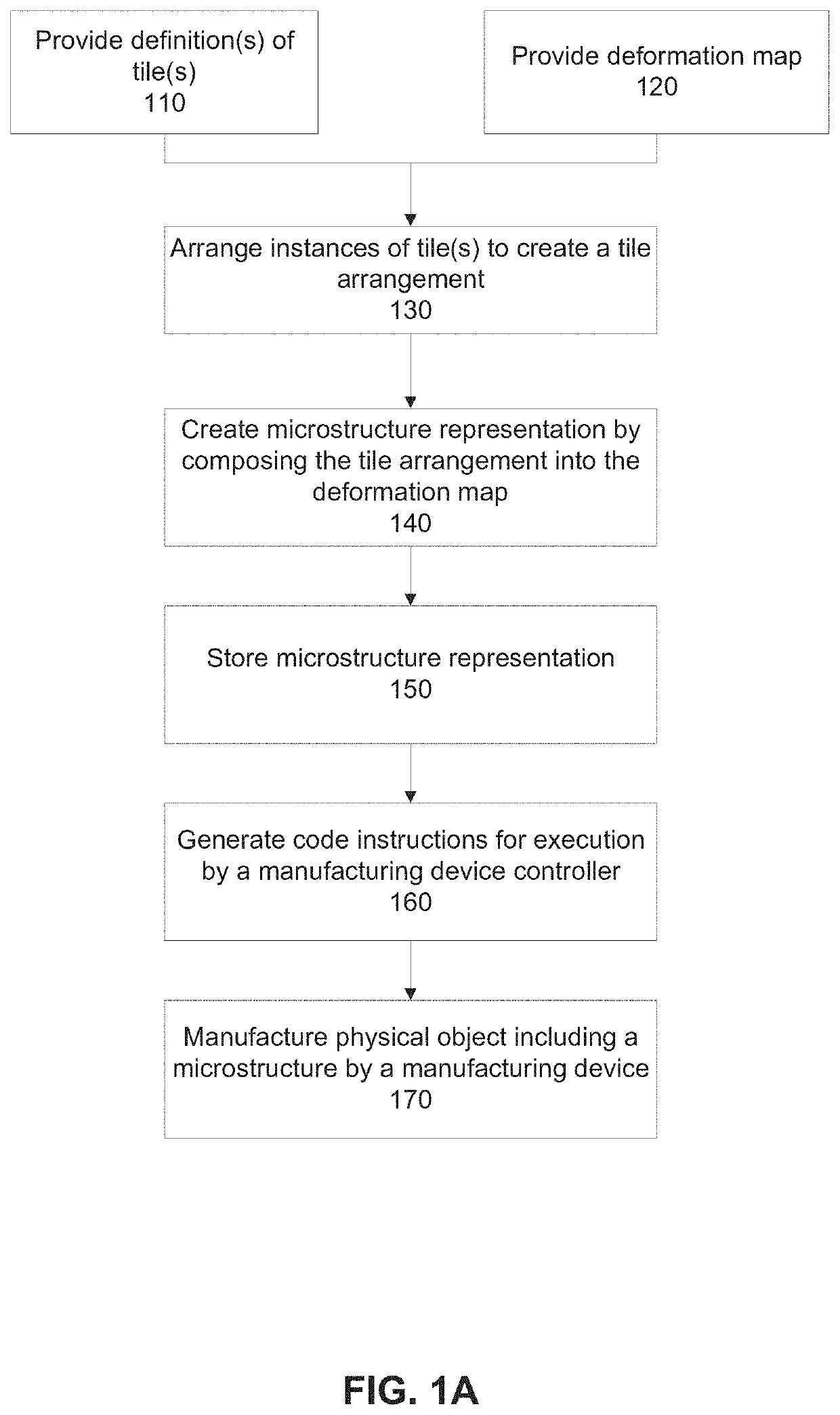
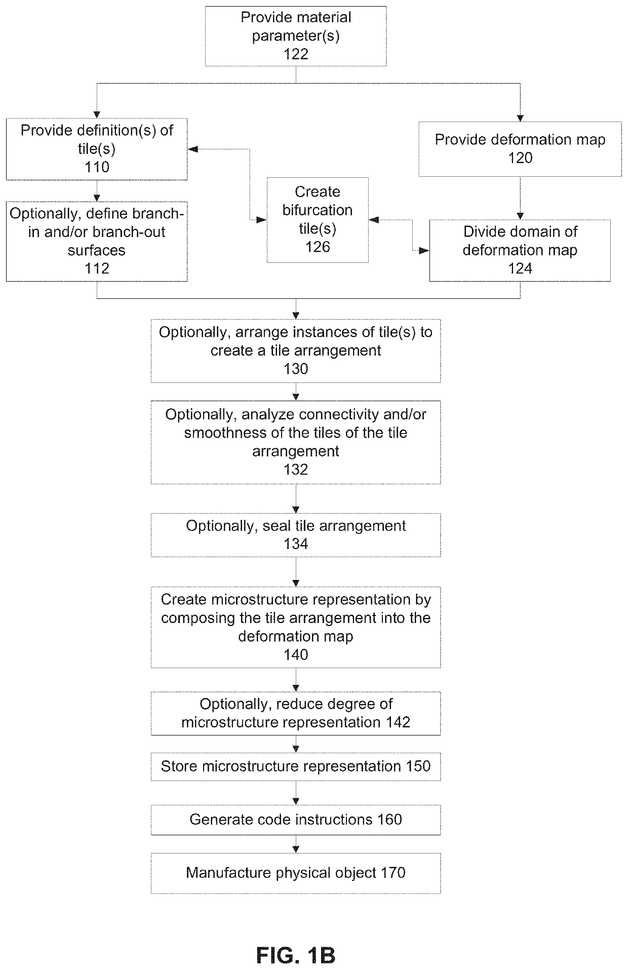
There is provided a method of generating instructions for manufacturing a microstructure by a manufacturing device, comprising: providing a representation of a freeform tile, providing a representation of a deformation map that maps a parameter space to a space of an object, arranging a plurality of instances of the freeform tile within at least a portion of a domain of the deformation map to create a tile arrangement, creating a representation a microstructure of the object by composing the tile arrangement into the deformation map, and providing code instructions for execution by a manufacturing device controller of a manufacturing device for manufacturing the microstructure.

Description

RELATED APPLICATIONS[0001]This application is a Continuation-In-Part (CIP) of U.S. Utility application Ser. No. 15 / 919,705 filed on Mar. 13, 2018, which claims the benefit of priority under 35 USC § 119(e) of U.S. Provisional Patent Application No. 62 / 470,399 filed on Mar. 13, 2017. The contents of the above applications are all incorporated by reference as if fully set forth herein in their entirety.FIELD AND BACKGROUND OF THE INVENTION[0002]The present invention, in some embodiments thereof, relates to microstructures and, more specifically, but not exclusively, to systems and methods for manufacturing a microstructure.[0003]Advances in additive manufacturing have enabled fabrication of a range of artifacts with complex and interesting properties. Use of composites, comprising of several materials, has grown rapidly. Microstructures are implemented in a wide range of applications, for example, aviation, and designing scaffold structures in tissue engineering, for example, as descr...

Claims


Application Information

Patent Timeline
Patent Type & Authority Patents(United States)
IPC IPC(8): G05B19/4099B33Y50/02G06T17/10G06T11/20G06T19/20A61B34/10A61F2/30G05B19/418
CPCG06T19/20B33Y50/02G05B19/4099G06T17/10G06T11/206A61B34/10G06T2219/2021G05B2219/35499G05B2219/35134G05B2219/49007A61F2002/30943G05B19/418
Inventor ELBER, GERSHONMASSARWI, FADYMACHCHHAR, JINESH
Owner TECHNION RES & DEV FOUND LTD
Learn More