Device for controlling inlet guide vanes by means of a multilayer piezoelectric actuator

a piezoelectric actuator and guide vanes technology, applied in the direction of climate sustainability, air transportation, jet propulsion plants, etc., can solve the problems of real disruption, unnecessary fuel heating, and unwanted power from the accessory gearbox, and achieve the effect of safe behavior

Active Publication Date: 2020-08-04
SAFRAN HELICOPTER ENGINES
View PDF9 Cites 20 Cited by
  • Summary
  • Abstract
  • Description
  • Claims
  • Application Information

AI Technical Summary

Benefits of technology

[0007]The present invention thus aims to mitigate the above-mentioned drawbacks by providing an efficient and optimized actuator solely for the function of controlling the IGVs and also presenting particularly safe behavior.

Problems solved by technology

Firstly, due to their reversibility, present-day hydraulic actuators do not have “position memory” or “fail freeze”, i.e. in the event of a failure they do not maintain the last controlled position.
Secondly, those actuators are dimensioned for a wide range of pressures and flow rates, which, due to interactions with the fuel circuit, causes real disruption to the fuel metering system each time fuel drives the actuator. The working pressure difference varies greatly depending on the engine operating point (low delta P when idling and high delta P at high speed). In addition, that overdimensioning has a non-negligible impact on the weight of the engine and causes unnecessary heating of the fuel and indirectly draws unwanted power from the accessory gearbox. Finally, those actuators are controllable only when the engine is in operation, which is particularly detrimental in the context of certain daily maintenance operations, such as engine endoscope inspections where the vanes need to be moved without starting the engine, since that requires the use of an external hydraulic unit.
However, the use of a brushless motor requires control electronics that are particularly complex and restrictive from a point of view of electromagnetic compatibility, and the powers involved are not sufficient under all flight conditions.

Method used


Image

  • Device for controlling inlet guide vanes by means of a multilayer piezoelectric actuator
  • Device for controlling inlet guide vanes by means of a multilayer piezoelectric actuator
  • Device for controlling inlet guide vanes by means of a multilayer piezoelectric actuator

Examples


Embodiment Construction

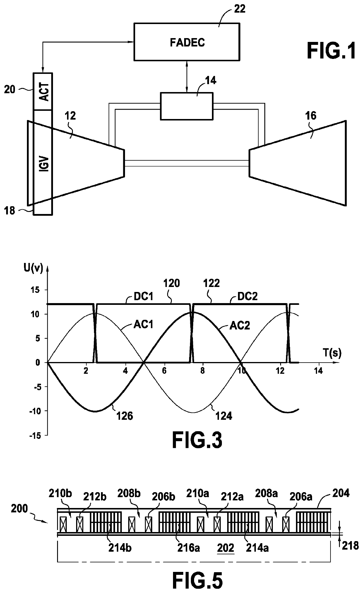
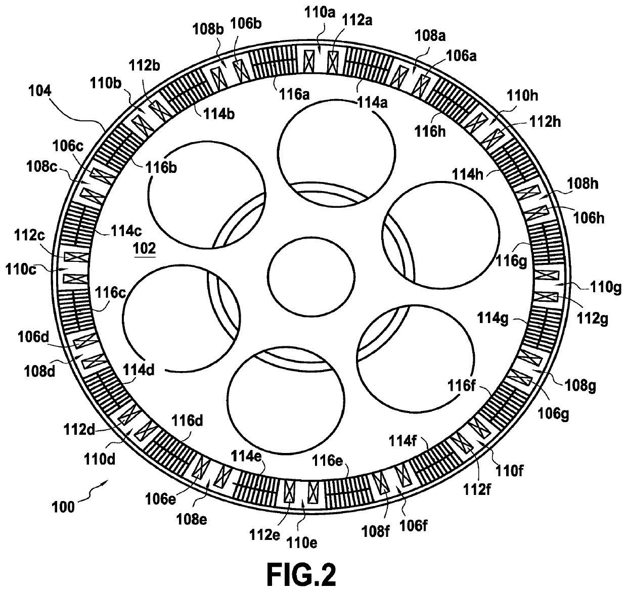
[0025]FIG. 1 is a diagram of a gas turbine engine 10 conventionally comprising a compressor 12, a combustion chamber 14, and a turbine 16 designed to drive the vanes of the engine (not shown). Inlet guide vanes (IGVs) 18 are arranged at the inlet of the compressor 12 and they are moved in rotation by one or more actuators (ACT) 20 controlled by a central computer (FADEC) 22 that also manages the engine and in particular the injection of gas into the combustion chamber. In the invention, the actuator of the inlet guide vanes is an electric actuator in the form of the particular rotary piezoelectric motor shown in FIG. 2.

[0026]The piezoelectric motor 100 comprises a central rotor 102 that surrounds an annular stator 104. The central rotor, which is advantageously perforated to save weight, is connected in fixed manner to the lever that actuates the inlet guide vanes, the lever having a pivot connection with the casing of the engine, whereas the stator has a fixed connection to a stati...


PUM


Abstract

An electric actuator for inlet guide vanes of a gas turbine engine, the electric actuator including a fixed portion secured to a stationary portion of the engine and a movable portion that is mechanically connected to the inlet guide vanes, stationary electromagnets distributed at regular intervals around the periphery of the movable portion and fastened to the fixed portion, and movable electromagnets arranged between the stationary electromagnets, each movable electromagnet being secured on either side to first and second piezoelectric elements, the movable electromagnets and the first and second piezoelectric elements having a degree of freedom of movement relative to the movable portion and having inside faces forming a common line of contact that is tangential to the movable portion.

Description

BACKGROUND OF THE INVENTION[0001]The present invention relates to the general field of compressors and turbines of aeroengines (in particular for airplanes or helicopters). More precisely the invention relates to controlling inlet guide vanes (IGVs) of a gas turbine engine.[0002]The actuators of the IGVs are used to control the position of the prerotation vanes situated upstream from the compressor stage(s) on helicopter turbine engines (see for example US 2014 / 0286745). The function of such an actuator consists in directing the flow of air entering the engine upstream from the compressor. Varying the angular position of the prerotation vanes makes it possible to optimize the overall performance of the engine (transients and specific consumption).[0003]The function of controlling the inlet guide vanes is usually provided by a hydraulic actuator powered by the fuel circuit having its flow rate and pressures directly indexed to the speed of the gas generator. However, such an architec...

Claims


Application Information

Patent Timeline
Patent Type & Authority Patents(United States)
IPC IPC(8): F01D17/24F01D17/16F01D9/04F02C9/20
CPCF01D9/041F01D17/162F01D17/24F02C9/20F05D2240/515Y02T50/60
Inventor VONFELT, JEAN-JULIEN CAMILLEKLONOWSKI, THOMASMOUTAUX, ANTOINE
Owner SAFRAN HELICOPTER ENGINES
Why Eureka
Try Eureka