Self-offsetting implantable catheter system

a catheter system and self-offsetting technology, applied in the direction of catheters, wound drains, etc., can solve the problems of mechanical shunt failure and malfunction in hydrocephalus treatment, ventricular catheters may become blocked or clogged, and the pores defined in the wall of the catheter closest to its free terminating end are particularly susceptible to undesirable blockage, so as to minimize obstruction and clogging of pores

Active Publication Date: 2020-08-11
INTEGRA LIFESCI SWITZERLAND SARL
View PDF31 Cites 0 Cited by
  • Summary
  • Abstract
  • Description
  • Claims
  • Application Information

AI Technical Summary

Benefits of technology

[0008]An aspect of the present invention is an improved implantable valve assembly including an improve catheter for the drainage of CSF or other bodily fluid having an extended operational lifespan that minimizes obstruction and clogging of the pores defined in the wall of the catheter.

Problems solved by technology

At tremendous cost to the health care system ranging in billions of dollars, each year tens of thousands of invasive brain surgeries are required to replace or revise hydrocephalus shunts that have malfunctioned due to mechanical failure.
Blockage, occlusion or clogging of the relatively small diameter pores defined in the wall of the catheter, primarily in the ventricular catheter, is the leading cause of mechanical shunt failure and malfunction in hydrocephalus treatment.
While there are several ways that the ventricular catheter may become blocked or clogged, obstruction is typically caused by growth of tissue, such as the choroid plexus, around the catheter and into the distal holes or pores.
Those pores defined in the wall of the catheter that are closest to its free terminating end are particularly susceptible to undesirable blockage due to its close physical proximity to the choroid plexus.
Despite such efforts, entry of the choroid plexus and other debris into the pores of the catheter may still occur partially or completely obstructing the openings and, in turn, hampering or even prohibiting removal of the catheter if blockage becomes to significant.
However, even when optimally positioned in the ventricle, drift over time may cause tissue in growth and obstruction of the drainage holes in the catheter.

Method used


Image

  • Self-offsetting implantable catheter system
  • Self-offsetting implantable catheter system
  • Self-offsetting implantable catheter system

Examples


Embodiment Construction

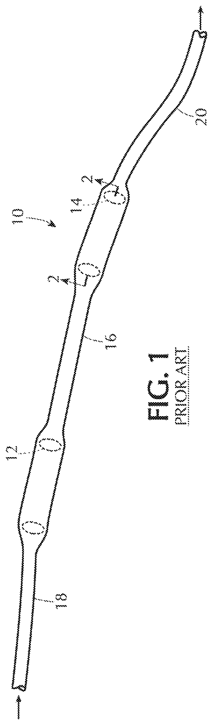
[0020]By way of illustrative example only, the present invention is Shown and described as an implantable catheter system for the drainage of a bodily fluid, for example, CSF. It is contemplated and within the intended scope of the present invention for the catheter system to be employed for the drainage of other types of bodily fluid.

[0021]The terms “proximal” / “proximally” and “distal” / “distally” refer to a direction closer to or away from, respectively, an operator (e.g., surgeon, physician, nurse, technician, user, etc.) who would insert the medical device into the patient, with the opposite tip-end (i.e., distal end or leading end) of the device inserted inside a patient's body. Thus, for example, a “proximal direction” would refer to the direction towards the operator, whereas “distal direction” would refer to the direction away from the operator towards the leading or tip-end of the medical device.

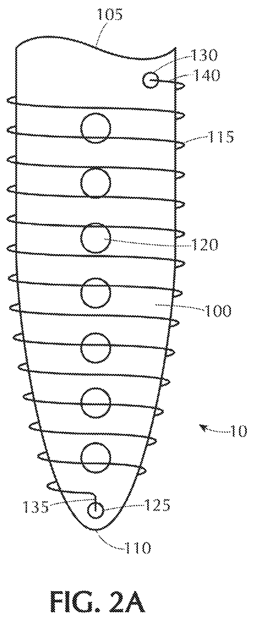
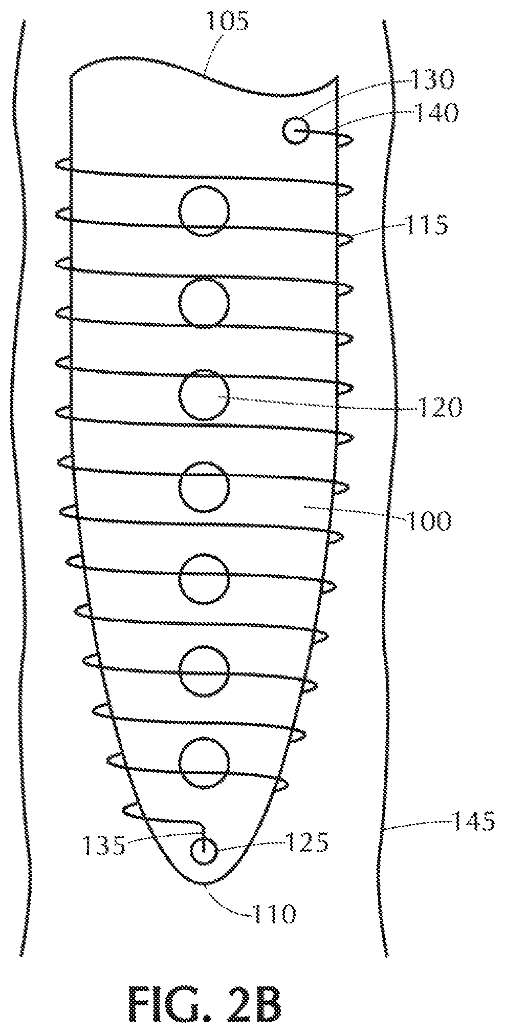
[0022]The location of the catheter is a significant factor in minimizing undesir...


PUM


Abstract

A self-offsetting implantable valve system including a catheter having an outer perimeter, a free terminating end and an opposite second end. A plurality of holes are defined proximate the free terminating end of the catheter. The system further including a self-offsetting memory component disposed radially about the outer perimeter of a portion of the catheter proximate the free terminating end of the catheter. This self-offsetting memory component is transitionable between a first state subject to application of an externally applied force and a second state free from the externally applied force. While in the first state at least a portion of the self-offsetting memory component having a diameter smaller than that same portion of the self-offsetting memory component while in the second state.

Description

BACKGROUND OF THE INVENTIONField of the Invention[0001]The present invention relates to an implantable catheter system including a catheter having a plurality of pores, holes or openings defined therein and method for using such system. More particularly, the invention relates to an improved catheter system for implantation in the body to drain a bodily fluid, in particular, cerebral spinal fluid (CSF). The present inventive catheter system is specifically designed, following implantation at a target site (e.g., ventricle) in the body, so that over time the catheter automatically remains offset from the ventricle wall, preferably substantially centered in the ventricle. The self-offsetting function of the present inventive catheter system minimizes undesirable obstruction or clogging of pores defined in the catheter that restricts the flow of fluid therethrough.Description of Related Art[0002]Catheters are used to perform various diagnostic and therapeutic procedures at target sites...

Claims


Application Information

Patent Timeline
Patent Type & Authority Patents(United States)
IPC IPC(8): A61M27/00A61M25/04A61M25/00
CPCA61M25/007A61M25/04A61M27/006
Inventor BODEN, JR., THOMASDEXTRADEUR, ALAN J.
Owner INTEGRA LIFESCI SWITZERLAND SARL
Why Eureka
Try Eureka