Method for monitoring and detecting the formation of degradation in at least one moving part of a rotating mechanism and associated system

a technology of rotating mechanism and movement part, applied in the direction of analysis of solids using sonic/ultrasonic/infrasonic waves, structural/machine measurement, processing detected response signals, etc., can solve the problems of false alarm generation and general inapplicability of monitoring rotary mechanisms

Active Publication Date: 2020-08-11
EUROCOPTER
View PDF11 Cites 0 Cited by
  • Summary
  • Abstract
  • Description
  • Claims
  • Application Information

AI Technical Summary

Benefits of technology

[0010]The present invention then aims to propose a method and device making it possible to do away with the aforementioned limitations. Furthermore, the method according to the invention can also make it possible to identify, in a faulty planetary reduction gearing, which planet gear has pronounced wear or any structural anomaly, such as a broken tooth, scaling of a rolling track or a hairline crack in formation.

Problems solved by technology

However, false alarms can be generated, then involving an unneeded stop, or even disassembly, for the rotary mechanism.
Furthermore, such methods are generally not suitable for monitoring rotary mechanisms for example including a planetary reduction gearing with several planet gears.

Method used


Image

  • Method for monitoring and detecting the formation of degradation in at least one moving part of a rotating mechanism and associated system
  • Method for monitoring and detecting the formation of degradation in at least one moving part of a rotating mechanism and associated system
  • Method for monitoring and detecting the formation of degradation in at least one moving part of a rotating mechanism and associated system

Examples


first embodiment

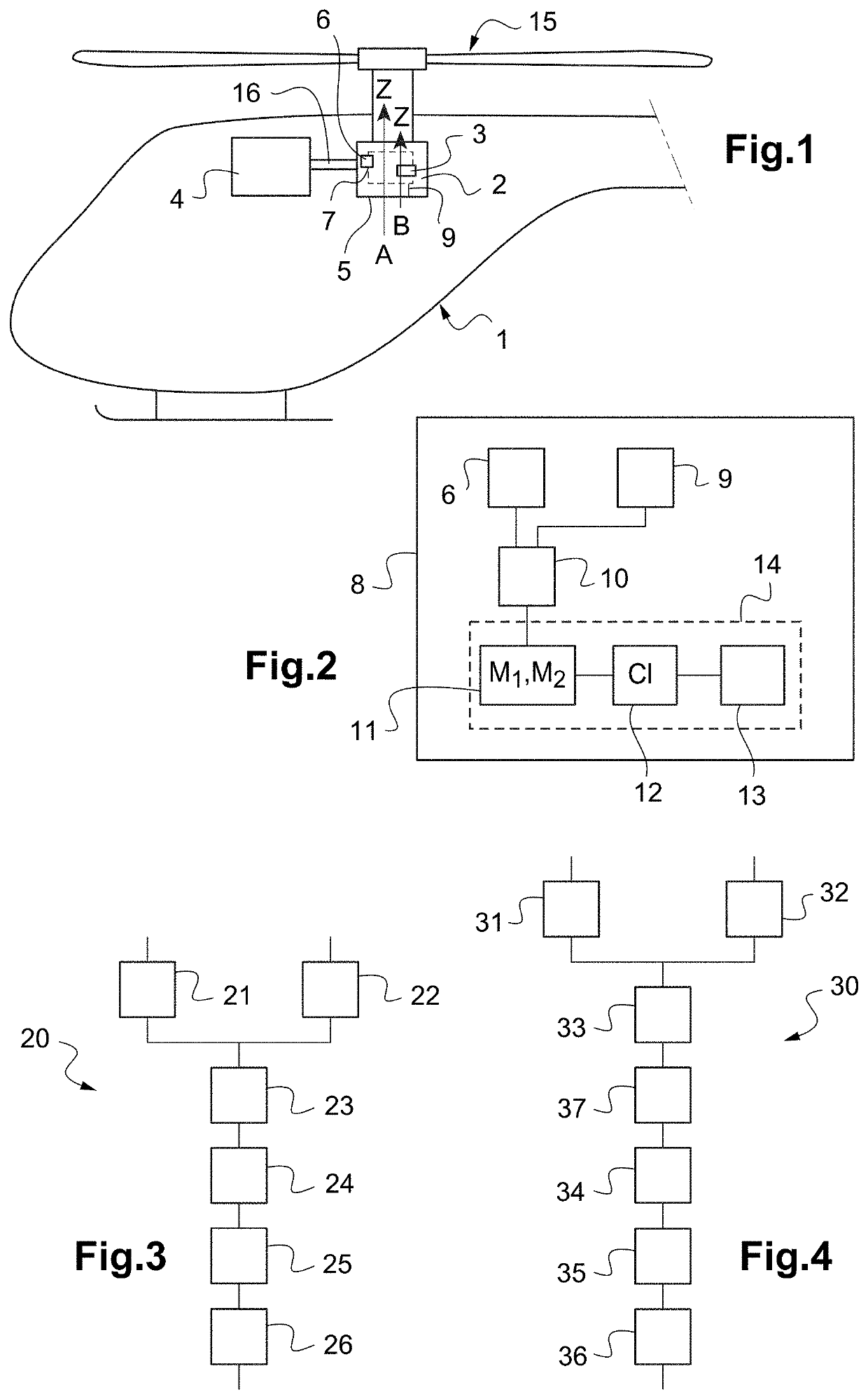
[0099]According to the invention illustrated in FIG. 3, a method 20 for monitoring and detecting the formation of damage in a moving part 3 of a rotary mechanism 2 thus includes a first measuring step 21 for measuring the accelerations of a fixed casing of the aircraft 1 during the operation of the rotary mechanism 2 using the vibrational sensor 6 and a second step 22 for measuring an angular position of the moving part(s) 3.

[0100]Such first and second measuring steps 21, 22 are for example carried out simultaneously and in parallel.

[0101]The method 20 next includes a preprocessing step 23 for calculating the synchronous variance of the vibrations measured over a cycle of a predetermined number n of rotations of the moving part(s) 3 around its (their) (respective) axis (axes) of rotation, a mapping step 24 for generating the at least two maps M1, M2, an analysis step 25 for the variations in the synchronous variance between the at least two successive maps M1, M2 and an alarm step 2...

second embodiment

[0102]According to the invention as shown in FIG. 4, a method 30 for monitoring and detecting the formation of damage in a moving part 3 of a rotary mechanism 2 may also include a first measuring step 31 for measuring the operating vibrations of the rotary mechanism 2 using the vibrational sensor 6 and a second measuring step 32 for measuring an angular position of the moving part(s) 3.

[0103]Like before, the method 30 next includes a preprocessing step 33 carried out in flight during a mission of the aircraft 1 for calculating the synchronous variance of the accelerations during the operation of the moving part(s) 3, a data transmission step 37 for transmitting data representative of the synchronous variance of the accelerations to the ground station 14.

[0104]Lastly like before, the method 30 then includes a mapping step 34 for generating at least two maps M1, M2, an analysis step 35 of the variations of the synchronous variance of the accelerations between the at least two successi...


PUM

PropertyMeasurementUnit
accelerationaaaaaaaaaa
currentaaaaaaaaaa
vibrationalaaaaaaaaaa

Abstract

A method for monitoring and detecting the formation of damage in at least one moving part of a rotary mechanism forming all or part of a kinematic transmission chain of an engine torque, the rotary mechanism equipping an aircraft, the method being implemented by a monitoring and detection system including at least one vibration sensor for measuring accelerations in at least one direction and generating a vibration signal as a function of time, the at least one vibration sensor being secured to a fixed casing of the aircraft and arranged near the rotary mechanism, at least one measuring member for measuring an angular position of the at least one moving part, each moving part including at least one degree of rotational freedom around a rotation axis.

Description

CROSS-REFERENCE TO RELATED APPLICATIONS[0001]This application claims priority to French patent application No. FR 1870202 filed on Feb. 26, 2018, the disclosure of which is incorporated in its entirety by reference herein.BACKGROUND OF THE INVENTION(1) Field of the Invention[0002]The present invention relates to the technical field of methods for monitoring wear, the formation of a hairline crack or fissure and / or a structural break in at least one moving part of a rotary mechanism. The rotary mechanism is also arranged in an aircraft, for example a rotorcraft, equipped with at least one engine, at least one primary rotor contributing to lift, or even also to the propulsion of the aircraft, and at least one primary power transmission gearbox.(2) Description of Related Art[0003]Furthermore, such a rotary mechanism then forms all or part of a kinematic transmission chain for an engine torque and may be arranged in the primary power transmission gearbox. The rotary mechanism may in par...

Claims


Application Information

Patent Timeline
Patent Type & Authority Patents(United States)
IPC IPC(8): G01N29/44G01N29/06G01M5/00G01M7/00B64F5/60
CPCG01N29/069G01M5/0016G01M7/00G01M5/0066B64F5/60G01M5/0033G01N29/44G01N2291/0289B64C27/006B64C27/12G01D21/02G08B21/182B64D2045/0085
Inventor MOREL, HERVERODRIGUEZ, JONATHAN
Owner EUROCOPTER
Why Eureka
Try Eureka