Rotary charging device for a shaft furnace

a charging device and shaft furnace technology, applied in the direction of furnaces, charge manipulation, lighting and heating apparatuses, etc., can solve the problems of minor drawbacks, less power transmission efficiency, and even more wear of the shaft furnace, so as to achieve more than compensate the minor drawbacks

Inactive Publication Date: 2010-02-04
PAUL WURTH SA
View PDF11 Cites 4 Cited by
  • Summary
  • Abstract
  • Description
  • Claims
  • Application Information

AI Technical Summary

Benefits of technology

[0005]The invention provides maintenance-friendly and reliable means for achieving electric energy transfer from the stationary part to the rotatable part in a rotary charging device for a shaft furnace.
[0007]According to the present invention, the rotary charging device comprises an inductive coupling device. This inductive coupling device includes a stationary inductor fixedly mounted to the stationary support and a rotary inductor fixedly mounted to the rotatable structure. The stationary and the rotary inductor are separated by a radial gap. They are configured for achieving contact-less electric energy transfer, from the stationary support to the rotatable structure, by means of a shared magnetic field coupled in radial direction trough the gap. Hence, the inductors constitute a rotary transformer. Thereby, the coupling device provides a maintenance-friendly and reliable means for powering an electric load arranged on said rotary structure and connected to the rotary inductor.
[0008]By virtue of its contact-less design, the rotary transformer-type, inductive coupling device is not subject to wear by attrition and therefore virtually maintenance-free. It will be understood that a known circular slip-ring arrangement adapted for a shaft furnace charging device will have a considerable diameter, because of the required central passage for charge material (burden), whereby its wear is even more pronounced. This problem is eliminated by virtue of the power transmission device according to the present invention. Although a slightly lesser degree of power transmission efficiency may result from the interferric gap, especially when compared to slip-ring arrangements, this minor drawback is more than compensated by the considerable improvements in reliability and maintenance-friendliness.
[0009]As opposed to axially opposed inductors, as used in known rotary transformers for weak current applications, e.g. signal transmission applications (e.g. in VCRs), the invention proposes to arrange the interferric gap in radial direction, i.e. opposing the pole faces of the inductors radially with reference to the axis of rotation. In the specific case of charging devices arranged on a shaft furnace, it has been found that the range of tolerance for motion of the rotatable structure is normally larger in vertical direction than in radial direction. Therefore, a radially opposed relationship of the inductors allows minimizing the interferric gap.
[0014]As will be appreciated by the skilled person, the inductive coupling device allows reliable and maintenance-friendly powering of an electric load, for example an electric motor operatively associated to the distribution chute for varying the angle of inclination of the distribution chute or for rotating the distribution chute about its longitudinal axis, of a cooling circuit pump, or any other electric load of considerable wattage (e.g. ≧500 W) arranged on the rotatable structure. For transmission of control and / or measurement signals it is not necessary to use the inductive coupling device. Instead, a radio transmitter, receiver or transceiver can be arranged on the rotatable structure for receiving and / or transmitting such signals to / from the load power by the coupling device.

Problems solved by technology

It will be understood that a known circular slip-ring arrangement adapted for a shaft furnace charging device will have a considerable diameter, because of the required central passage for charge material (burden), whereby its wear is even more pronounced.
Although a slightly lesser degree of power transmission efficiency may result from the interferric gap, especially when compared to slip-ring arrangements, this minor drawback is more than compensated by the considerable improvements in reliability and maintenance-friendliness.

Method used


Image

  • Rotary charging device for a shaft furnace
  • Rotary charging device for a shaft furnace
  • Rotary charging device for a shaft furnace

Examples


Embodiment Construction

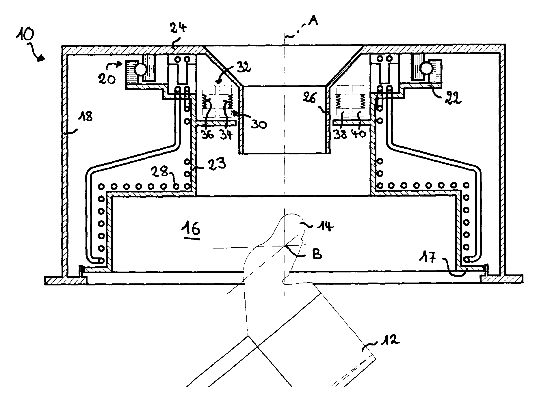
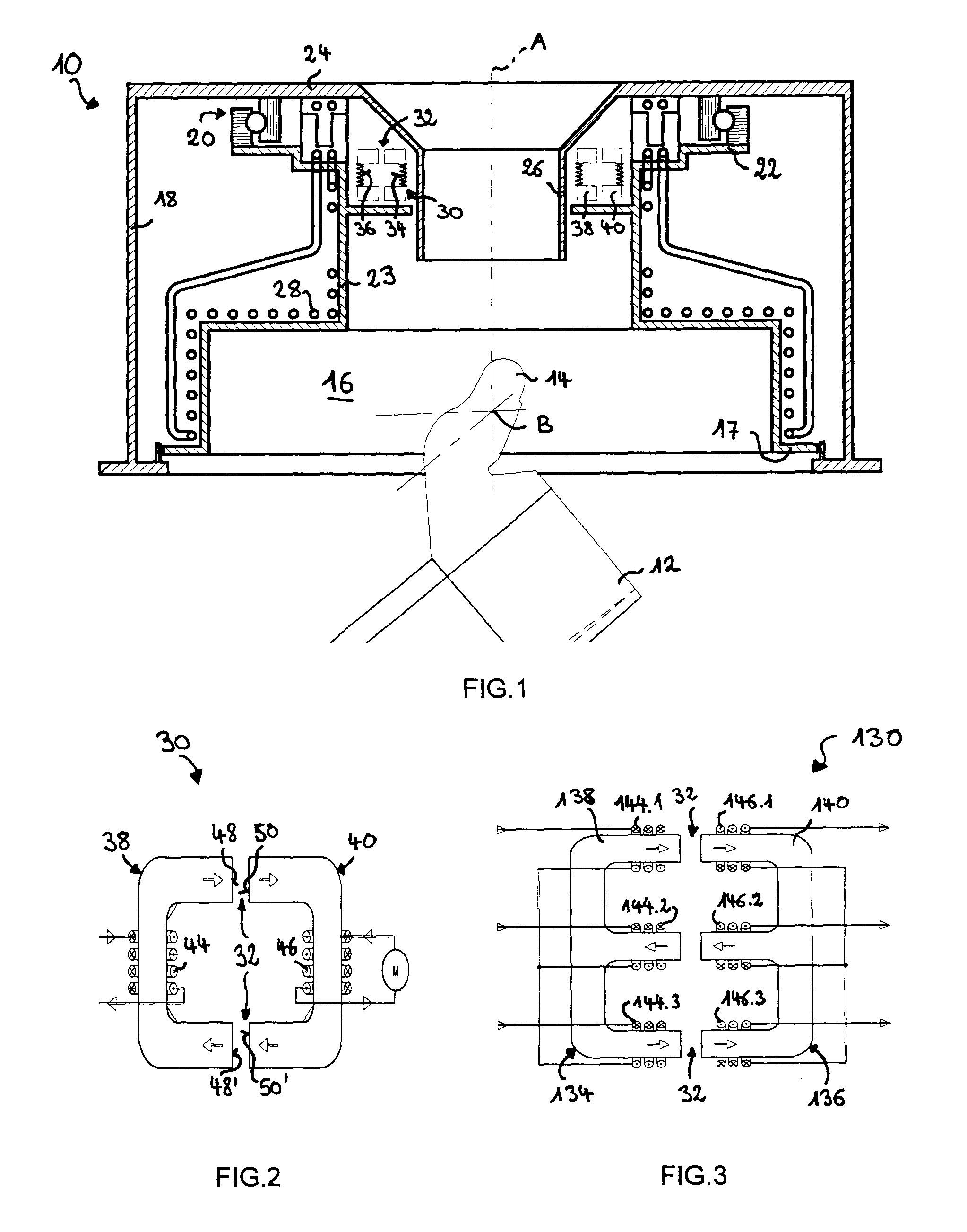
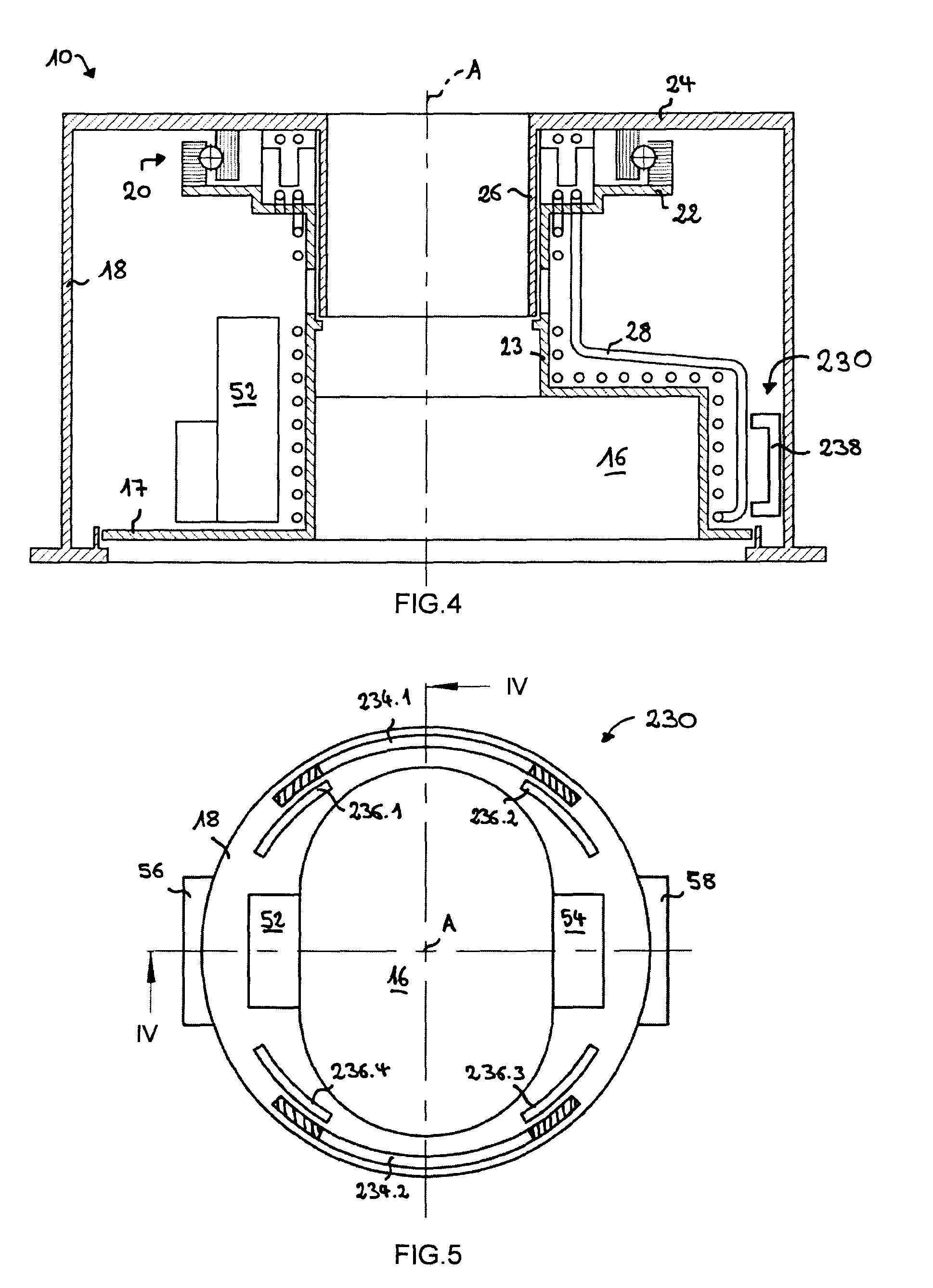
[0027]In FIG. 1, reference number 10 generally identifies a rotary charging device. The rotary charging device 10 will typically be installed on the throat of a shaft furnace (not shown) and in particular of a blast furnace for pig iron production. This charging device 10 comprises a rotary distribution means for distributing charge material on a charging surface in the hearth of the furnace. As part of the rotary distribution means, FIG. 1 shows a pivotable distribution chute 12 that is connected by means of duckbill-shaped mounting members 14 to a rotatable structure 16. The rotatable structure 16 has a lower support platform 17 (see FIG. 4) that supports an axle, forming axis B, on which the distribution chute 12 is suspended.

[0028]As seen in FIG. 1, the rotary charging device 10 also has a stationary support conceived as a housing 18. The rotatable structure 16 is rotatably supported in the housing 18 by means of large diameter roller bearings 20. The outer race of roller bearin...


PUM

PropertyMeasurementUnit
power consumptionaaaaaaaaaa
radial widthaaaaaaaaaa
electric poweraaaaaaaaaa

Abstract

A rotary charging device (10) for a shaft furnace commonly comprises a rotary distribution means (12) for distributing charge material on a charging surface in the shaft furnace. A rotatable structure supports (16) the rotary distribution means and a stationary support (18) rotatably supports the rotatable structure. According to the invention, the charging device (10) is equipped with an inductive coupling device (30) including a stationary inductor (34) fixed to the stationary support and a rotary inductor (36) fixed to the rotatable structure. The stationary inductor (34) and the rotary inductor (36) are separated by a radial gap and configured as rotary transformer for achieving contact-less electric energy transfer from the stationary support (18) to the rotatable structure (16) by means of magnetic coupling trough the radial gap for powering an electric load arranged on the rotatable structure (16) and connected to said rotary inductor (36).

Description

TECHNICAL FIELD OF THE INVENTION[0001]The present invention generally relates to a rotary charging device for a shaft furnace such as a metallurgical blast furnace. More particularly, the invention relates to achieving electric energy transfer from the stationary part to the rotatable part of the charging device.BRIEF SUMMARY OF RELATED ART[0002]Today, many metallurgical blast furnaces are equipped with a rotary charging device for feeding charge material into the furnace. Charging devices of the BELL LESS TOP type represent a particularly widespread example. Such a rotary charging device typically comprises a variably inclinable chute that is mounted on a rotatable support. In most currently used charging devices of this type, the variation of the chute inclination is achieved by means of a highly developed drive gear mechanism configured to transfer mechanical work from the stationary to the rotating part for varying the chute inclination.[0003]In EP 0 863 215 it has been proposed...

Claims


Application Information

Patent Timeline
Patent Type & Authority Applications(United States)
IPC IPC(8): C21B7/20B23P6/00
CPCC21B7/20Y10T29/49718F27D3/0033F27B1/20
Inventor BREDEN, EMILEHAUSEMER, LIONELLONARDI, EMILETHILLEN, GUY
Owner PAUL WURTH SA
Why Eureka
Try Eureka