Structures for modifying leaky mode light

a technology of leaky mode and light, applied in the field of structures for modifying leaky mode light, can solve the problems of difficult and expensive fabrication of gratings in leaky mode devices, large apertures, thicker, etc., and achieve the effect of increasing the view zone and increasing the field of view

Active Publication Date: 2020-08-11
BRIGHAM YOUNG UNIV
View PDF1 Cites 3 Cited by
  • Summary
  • Abstract
  • Description
  • Claims
  • Application Information

AI Technical Summary

Problems solved by technology

Larger apertures mean thicker, more expensive, harder-to-process devices.
Additionally, fabricating gratings in leaky mode devices can be difficult and expensive when gratings have high spatial frequency.
However, output gratings in lithium niobate meant to outcouple leaky mode light typically have grating periods around 300 nm.
But these fabrication techniques are difficult, expensive, and suffer from other shortcomings.
Interference lithography has limited control of the grating pattern (only uniform gratings).
Contact lithography requires special, thin, fragile flex masks that degrade with use.
Ebeam lithography writes the pattern serially and is considered a low-throughput, high cost technique.
Another problem is that a bottom exit grating will reduce the field of view of a leaky mode near-eye display as compared with an edge-exit leaky mode display.

Method used


Image

  • Structures for modifying leaky mode light
  • Structures for modifying leaky mode light
  • Structures for modifying leaky mode light

Examples


Embodiment Construction

[0025]This Application claims priority as a continuation-in-part to U.S. Non-provisional application Ser. No. 15 / 955,670, titled “Structures for Modifying Leaky Mode Light,” the first inventor of which is Daniel Smalley, which was filed on Apr. 17, 2018, and which in turn claims priority to U.S. Provisional Application No. 62 / 486,326, titled “Structures for Modifying Leaky Light Mode,” the first inventor of which is Daniel Smalley, which was filed on Apr. 17, 2017, and which is incorporated herein by reference in its entirety.

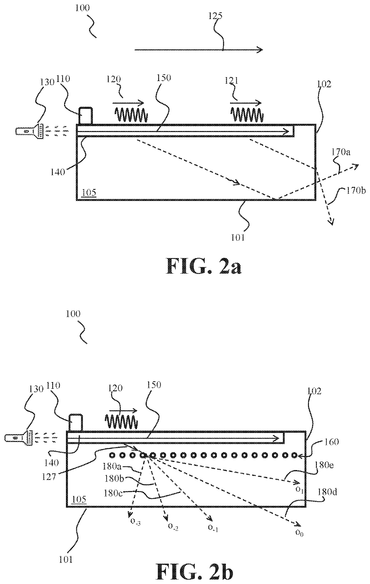
[0026]A system and method are disclosed for using structures to redirect leaky mode light to bottom exit instead of side exit, and further to split light from illuminated SAWs into different orders, and further to overcome and / or mitigate drawbacks associated with bottom exit leaky mode light for flat-screen and near-eye architectures.

[0027]Table of Reference Numbers from Drawings:

[0028]The following table is for convenience only, and should not be construed to...


PUM

PropertyMeasurementUnit
sizeaaaaaaaaaa
grating periodsaaaaaaaaaa
timeaaaaaaaaaa

Abstract

A method and system for using laser-induced structures to direct light to exit the bottom of a leaky mode device, and further to divide leaky mode light into multiple orders, and to implement one or more pulsing / strobing patterns such that a field of view is increased for a viewer, or the view zone is increased for a viewer. A leaky mode device may comprise a substrate, a surface acoustic wave (“SAW”) transducer, a waveguide having a higher refractive index than the substrate, an input region for input light, and laser induced structures such as grating. The SAW transducer may be positioned on a top surface of the substrate, and may be configured to emit a SAW wave to propagate across the substrate. The waveguide may be positioned below the SAW. The input wave region may be configured to couple light onto the waveguide. When light is coupled onto the waveguide, the refractive index may change such that the light in the waveguide exits the waveguide as leaky mode light and interacts with the laser-induced grating, which is below the waveguide. The laser-induced grating is configured to divide the leaky mode light into multiple orders, each bent at a different angle.

Description

BACKGROUND OF THE INVENTION[0001]Leaky mode systems may be used for holographic video, e.g., flat-screen, scanned aperture, and near-eye holographic video systems. In a leaky mode system, which generally comprises multiple leaky mode devices, surface acoustic waves (“SAW”) for a leaky mode device are generated by a transducer that encodes electrical information as a pattern of surface acoustic waves. This surface acoustic wave pattern acts both to mode couple light so that it is no longer guided and also to encode the light with holographic information. The leaky mode light propagates to form part or all of a holographic image.[0002]One of the shortcomings in leaky mode light systems is that light exits the edge, rather than the bottom, of the device. This means that the device output aperture depends on the device thickness. Larger apertures mean thicker, more expensive, harder-to-process devices. Because in existing leaky light mode devices light exits the edge, but not the bottom...

Claims


Application Information

Patent Timeline
Patent Type & Authority Patents(United States)
IPC IPC(8): G02F1/335G02F1/125G02B6/122G02B6/02H01S3/094G02B27/01G02F1/01H03H9/02
CPCG02F1/335G02B6/1223G02F1/125G02B6/02076G02F1/0126H03H9/02543H01S3/094046G02B27/017G02B27/0172G02B2027/0174
Inventor SMALLEY, DANIEL
Owner BRIGHAM YOUNG UNIV
Why Eureka
Try Eureka