
Structure member specification device and structure member specification method

a technology of structure member and specification device, which is applied in the direction of instruments, television systems, image enhancement, etc., to achieve the effect of efficiently creating inspection records and easy and accurate acquisition

Active Publication Date: 2020-08-18
FUJIFILM CORP
View PDF19 Cites 0 Cited by
  • Summary
  • Abstract
  • Description
  • Claims
  • Application Information

AI Technical Summary

Benefits of technology

The present invention provides a device and method for identifying structure members in an image of a structure captured by an imaging device during inspection. This allows for easier and accurate acquisition of member identification information and efficient creation of an inspection record.

Problems solved by technology

This is troublesome.

Method used


Image

  • Structure member specification device and structure member specification method
  • Structure member specification device and structure member specification method
  • Structure member specification device and structure member specification method

Examples


first embodiment

of Member Identification Information Acquisition

[0109]The member identification information acquisition unit 326 acquires, from the member table 332, the member identification information for uniquely specifying the member included in the image captured by the twin-lens camera 202 on the basis of the second space information input from the transformation unit 324 (information indicating the plane equation indicating the measurement plane in the bridge coordinate system, and the measurement plane range) and the information stored in the member table 332.

[0110]The member table 332 is described now.

[0111]In the member table 332, space information on each member that constitutes the bridge in the bridge coordinate system (third information) and member identification information indicating each member are registered in an associated manner. For the third space information on each member, for example, a drawing plane range of each member, or a drawing plane showing the drawing plane range...

second embodiment

of Member Identification Information Acquisition

[0140]In a second embodiment of member identification information acquisition, the measurement plane range illustrated in FIG. 9 is compared with a drawing plane range (see Expression 6) of each member registered in the member table 332, the corresponding member is specified by extracting the drawing plane range that is the most approximate to the measurement plane range, and acquires the member identification information (element number) registered in association with the specified member.

[0141]While the members are narrowed down by using the plane equation in the first embodiment, the estimation accuracy for the drawing plane is higher in the first embodiment than that of the second embodiment, and hence the measurement accuracy for the plane range may be lower in the first embodiment than that of the second embodiment.

third embodiment

of Member Identification Information Acquisition

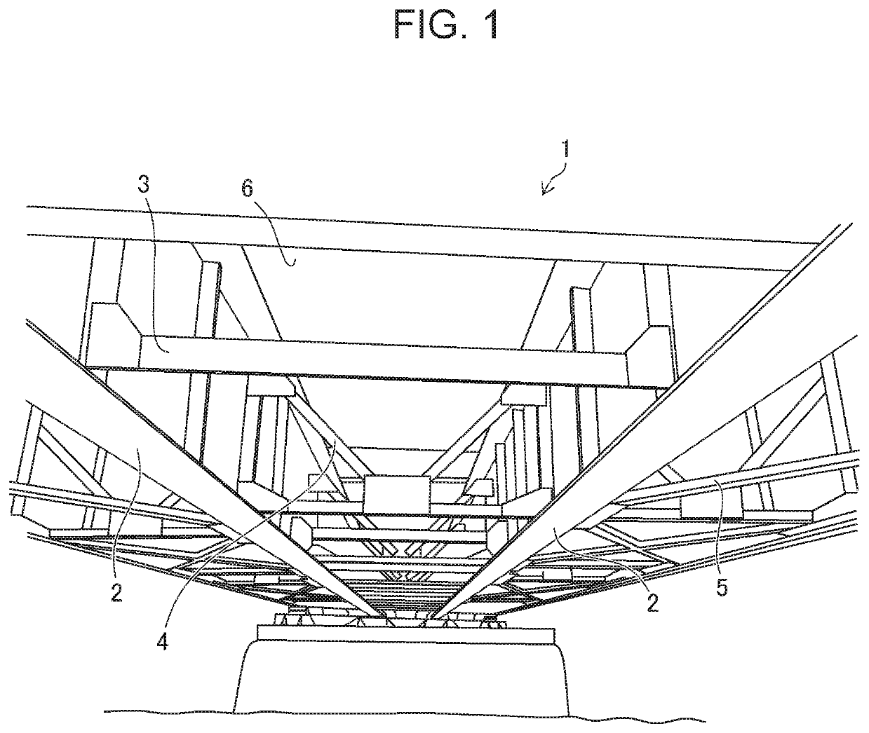
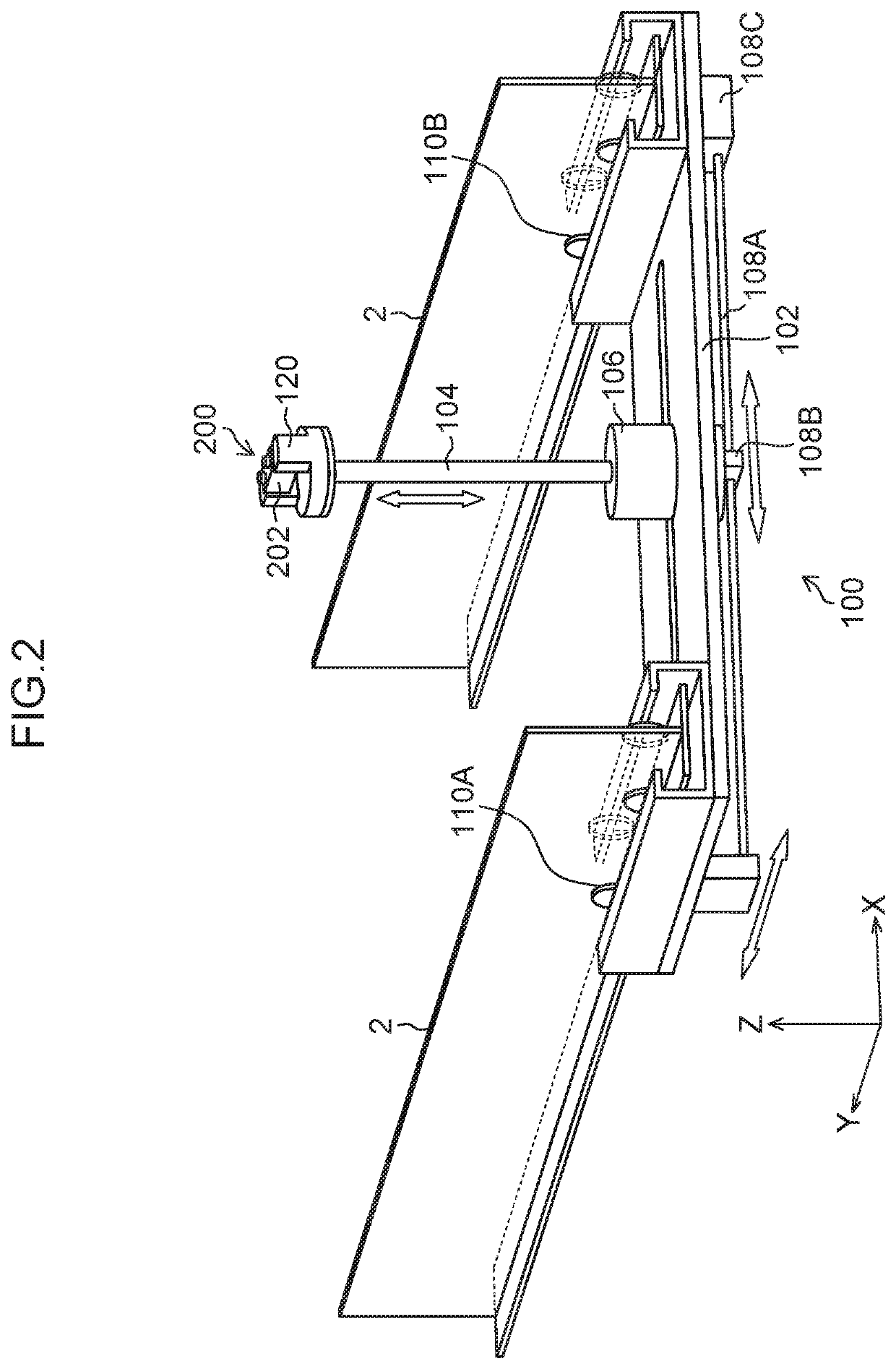
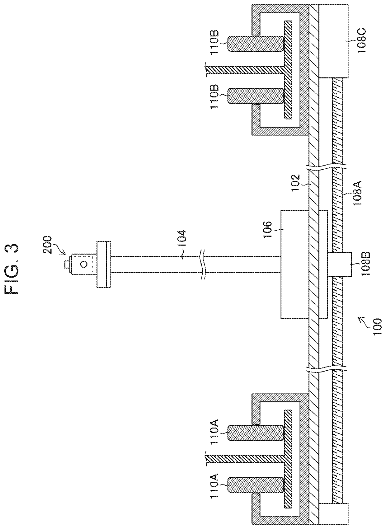
[0142]In a third embodiment of member identification information acquisition, member identification information (member type+element number) on a member to be measured that can be image captured from the position (imaging position) of the twin-lens camera 202 mounted on the robot device 100 as illustrated in FIG. 18 is associated with a panel (coffer) of the bridge 1 where the twin-lens camera 202 is located and registered in the member table 332 in advance.

[0143]For example, FIG. 18 illustrates panels C13, C14, C23, and C24 of the bridge 1. When the twin-lens camera 202 is located in the panel C24, the members (member types and element numbers) that can be image captured at this position are as follows.

[0144]Main girders: Mg0204, Mg0304

[0145]Cross beam: Cr0204

[0146]Lower lateral frame: Ll0204

[0147]By detecting the panel in which the twin-lens camera 202 is located from a plurality of panels of the bridge 1 in accordance with the posit...


PUM


Abstract

The present invention provides a structure member specification device and a structure member specification method capable of easily and accurately acquiring member identification information indicating a member included in an image of a structure captured by an imaging device when the structure is inspected. The structure member specification device acquires first space information on the structure in a local coordinate system image captured by an imaging device, and transforms the acquired first space information into second space information in a global coordinate system; prepares a member table in which third space information on each member that constitutes the structure in the global coordinate system and member identification information indicating each member are registered in an associated manner; specifies, on the basis of the transformed second space information and the third space information registered in the member table, the third space information corresponding to the second space information; and acquires member identification information corresponding to the specified third space information.

Description

CROSS-REFERENCE TO RELATED APPLICATIONS[0001]The present application is a Continuation of PCT International Application No. PCT / JP2016 / 084643 filed on Nov. 22, 2016 claiming priority under 35 U.S.C § 119(a) to Japanese Patent Application No. 2016-000894 filed on Jan. 6, 2016. Each of the above applications is hereby expressly incorporated by reference, in their entirety, into the present application.BACKGROUND OF THE INVENTION1. Field of the Invention[0002]The present invention relates to a structure member specification device and a structure member specification method, and more particularly relates to a technology for specifying a member that constitutes a structure such as a bridge.2. Description of the Related Art[0003]A social infrastructure such as a bridge needs to be periodically inspected. When a structure is inspected, “an inspected member” and “an element number (position) of an element in the member” need to be written in an inspection record with an image (photograph) ...

Claims


Application Information

Patent Timeline
Patent Type & Authority Patents(United States)
IPC IPC(8): G06T7/00G06Q50/08E01D19/10G06T7/70G06Q10/00G01M5/00H04N13/204H04N13/207H04N13/271G06T7/579G06T7/521H04N5/225
CPCE01D19/106G06T7/0002G01M5/0033H04N13/204G06Q50/08G01M5/0075G06T7/70G01M5/0091G06Q10/20H04N5/225G06T7/521G06T7/579G06T2207/10012G06T2207/10028G06T2207/30184H04N13/207H04N13/271H04N23/00
Inventor KIKUCHI, HIROAKI
Owner FUJIFILM CORP
Learn More