Method and device for uplink transmission based on network communication

a network communication and uplink technology, applied in the field of radio signal transmission methods, can solve the problems of reducing transmission efficiency, increasing uplink transmission delay, affecting certain performance, etc., and achieves the effect of reducing transmission delay, not reducing power consumption, and increasing the standby time of the u

Active Publication Date: 2020-08-18
HONOR DEVICE CO LTD
View PDF8 Cites 1 Cited by
  • Summary
  • Abstract
  • Description
  • Claims
  • Application Information

AI Technical Summary

Benefits of technology

[0009]In one embodiment, the inventors have found through researches that one of the advantages of CB uplink transmission is that the CB uplink transmission can effectively reduce both the overhead and the collision of control signalings when the number of users required to be served by the base station is in large number and the time-frequency resources required by each user are less. However, the CB uplink transmission obviously causes interference between users, which in turn affects certain performance. Meanwhile, when the number of UEs is small, or the uplink data packet to be transmitted has high requirements for robustness, the UE under the CB uplink transmission may also transfer to Grant Based (GB) uplink transmission to improve performance. Therefore, when the UE changes the CB uplink transmission to the GB uplink transmission, the base station needs to obtain corresponding information. At the same time, considering the problem of reducing the complexity of the terminal device and reducing the power consumption, when the transmission mode changes, the UE does not need to monitor the downlink control signaling in each subframe like the traditional UE.

Problems solved by technology

the signaling required for downlink scheduling can seriously reduce transmission efficiency, and in particular, it is considered that a typical number of information bits included in the uplink transmission for an IoT device is usually small;
the uplink transmission delay is increased, wherein in some special scenarios, IoT communication requires lower transmission delays, while the existing scheduling-based uplink transmission cannot meet this requirement.
However, the CB uplink transmission obviously causes interference between users, which in turn affects certain performance.
In one embodiment, in the above method, although the base station configures the first resource pool, the base station does not determine where the target time-frequency resources are located in the first resource pool, and also does not know how many terminals in the target time-frequency resources will transmit upstream data.

Method used


Image

  • Method and device for uplink transmission based on network communication
  • Method and device for uplink transmission based on network communication
  • Method and device for uplink transmission based on network communication

Examples


embodiment 1

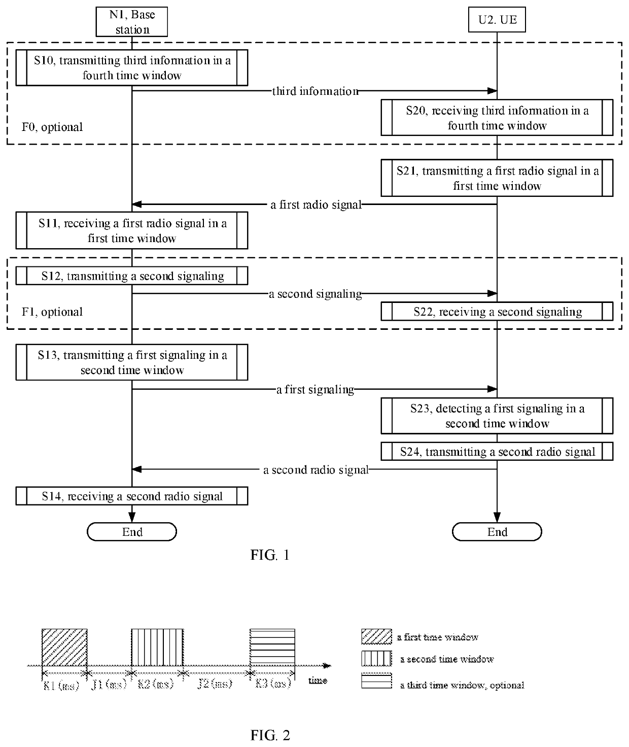
[0185]Embodiment 1 illustrates a flow chart of uplink transmission, as shown in FIG. 1. In FIG. 1, base station N1 is the maintenance base station of the serving cell of UE U2, and the steps identified in block F0 and block F1 are optional, respectively.

[0186]The base station N1 transmits third information in a fourth time window in step S10, receives a first radio signal in a first time window in step S11, transmits a second signaling in step S12, transmits a first signaling in a second time window in step S13, and receives a second radio signal in step S14.

[0187]The UE U2 receives third information in a fourth time window in step S20, transmits a first radio signal in a first time window in step S21, receives a second signaling in step S22, detects a first signaling in a second time window in step S23, and transmits a second radio signal in step S24.

[0188]In Embodiment 1, the first radio signal comprises at least first information between first information and first data; the firs...

embodiment 2

[0196]Embodiment 2 is a schematic diagram illustrating the relative positions of the first time window, the second time window and the third time window according to an embodiment of the present disclosure, as shown in FIG. 2. In FIG. 2, the oblique line identifies the first time window, the vertical line identifies the second time window, and the horizontal line identifies the third time window, wherein the third time window is optional.

[0197]In FIG. 2, the second time window is behind the first time window in the time domain, and the third time window is behind the second time window in the time domain. The first time window occupies K1 (ms) in the time domain, the second time window occupies K2 (ms) in the time domain, and the third time window occupies K3 (ms) in the time domain. The end time of the first time window is spaced from the start time of the second time window by J1 (ms), and the end time of the second time window is spaced from the start time of the third time windo...

embodiment 3

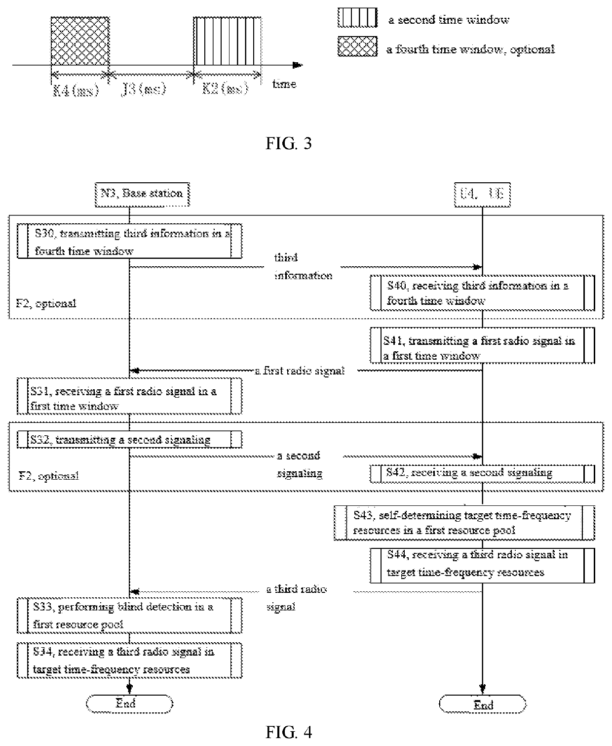
[0198]Embodiment 3 illustrates a schematic diagram illustrating the relative positions of the second time window and the fourth time window according to an embodiment of the present disclosure, as shown in FIG. 3. In FIG. 3, the vertical line identifies the second time window and the cross line identifies the fourth time window, wherein the fourth time window is optional.

[0199]As shown in FIG. 3, the second time window is behind the fourth time window in the time domain, and the second time window occupies K2 (ms) in the time domain, and the fourth time window occupies K4 (ms) in the time domain. The end time of the fourth time window is spaced from the start time of the second time window by J3 (ms), where K2, K4 and J3 are all positive integers.


PUM


Abstract

The present disclosure discloses a method and device in wireless communication. The UE transmits the first radio signal in a first time window. The first radio signal comprises at least first information of first information and first data. The first information is used to determine whether the UE detects the first signaling in a second time window. In the present disclosure, the UE indicates whether the first signaling is detected at a subsequent time by the first radio signal. The present disclosure can reduce the number of blind detections performed by the UE, reduce the complexity of the UE, save power consumption of the UE, and prolong the standby time of the UE.

Description

CROSS REFERENCE TO RELATED APPLICATION[0001]This application is a continuation of International Application No. PCT / CN2017 / 080766, filed Apr. 17, 2017, claiming the priority benefit of Chinese Patent Application Serial Number 201610321422.8, filed on May 14, 2016, the full disclosures of which are incorporated herein by reference.BACKGROUNDTechnical Field[0002]The present disclosure relates to a method for transmitting radio signals in a wireless communication system, and in particular to a method and device for uplink transmission based on cellular network communication.Related Art[0003]In a conventional digital modulation-based wireless communication system, such as a 3rd Generation Partner Project (3GPP) cellular system, uplink radio signals are sent based on scheduling of a base station. For the next generation of wireless communication systems, Internet of Things (IoT) communication may become an important application scenario.[0004]The characteristics of the IoT communication ...

Claims


Application Information

Patent Timeline
Patent Type & Authority Patents(United States)
IPC IPC(8): H04L1/00H04W72/04H04L1/18H04L1/16H04L27/26H04L5/00
CPCH04L1/0026H04L1/001H04W72/0446H04L1/0004H04L1/0025H04L1/1896H04L1/1812H04L1/1671H04L1/1657H04L27/2602H04L1/1822Y02D30/70H04L5/0091H04L1/0027H04L1/1864H04W72/23
Inventor ZHANG, XIAOBO
Owner HONOR DEVICE CO LTD
Why Eureka
Try Eureka