
Continuous casting method

a casting method and continuous technology, applied in casting apparatus, melt-holding vessels, manufacturing tools, etc., can solve the problems of unavoidable containment of molten steel discharged from the submerged nozzle, and achieve the effects of preventing clogging of the nozzle, stable and significant reduction of entrainment, and high quality

Active Publication Date: 2020-08-25
NIPPON STEEL STAINLESS STEEL CORP
View PDF10 Cites 0 Cited by
  • Summary
  • Abstract
  • Description
  • Claims
  • Application Information

AI Technical Summary

Benefits of technology

[0025]The application of the measure of the invention enables stable and significant decrease of the entrainment of foreign matters into the solidification shell, which unavoidably occurs in continuous casting of steel. In the case where argon gas is used as a seal gas for a tundish or as a gas for preventing clogging of a nozzle, bubbles of argon gas can be significantly prevented from being mixed in as foreign matters. According to the invention, therefore, a cold rolled steel sheet having high quality with significantly less surface defects caused by the foreign matters can be obtained without any particular mechanical or chemical removal treatment applied to the surface of the cast piece or the hot rolled steel sheet. The continuous casting method of the invention is particularly effective when applying to a stainless steel, which is desired to have a good surface appearance.

Problems solved by technology

The molten steel discharged from the submerged nozzle unavoidably contains bubbles, non-metallic particles, and the like mixed therein.

Method used


Image

  • Continuous casting method
  • Continuous casting method

Examples


example 1

[0051]The ferritic stainless steels having the chemical compositions shown in Table 1 were cast with a continuous casting apparatus to produce cast pieces (slabs).

[0052]

TABLE 1Chemical composition (% by mass)Steel No.CSiMnNiCrCuMoTiAlNbVNOthers10.0750.5860.4290.1716.13——————0.018—20.0610.4000.2600.1216.01——————0.011—30.0610.6800.4400.1216.280.030.060.0120.005—0.1600.016—40.0060.4920.1890.1511.13——0.2350.060——0.008—50.0060.0900.1000.1517.820.041.040.3520.033—0.0700.012—60.0030.2550.1530.1615.410.060.510.2500.103—0.0540.010B: 0.00170.0060.0400.1600.1717.580.070.910.2680.182—0.0700.013—80.0630.4200.7600.1416.140.060.170.003——0.1200.035—90.0040.0500.0700.1218.140.041.050.2620.246—0.0500.012Zr: 0.10100.0060.0700.1200.1917.650.050.920.2710.267—0.0600.010—110.0100.5400.3300.3319.930.470.05——0.358—0.011—120.0100.4700.3500.2619.040.570.02——0.354—0.013—130.0670.4400.8500.1316.190.070.10———0.1500.026—140.0080.0800.2600.1411.510.060.090.2500.030—0.0400.007—150.0730.6560.3240.1616.12——————0.016—...

example 2

[0065]The influence of the electro-magnetic stirrer on the effect of suppressing the entrainment of foreign matters was investigated by utilizing a part of the ingot charges shown in Table 2A. The continuous casting conditions and the state of defect occurrence of the cold rolled annealed steel sheets are shown in Table 3. The items shown therein the same as in Table 2A. The numeral of the example No. in Table 3 corresponds to the numeral of the example No. in Table 2A, and the examples with the same numeral uses the same ingot charge. Only the electro-magnetic stirrer condition was changed stepwise for the same ingot charge, and coils of cold rolled annealed steel sheets were produced in the same manner as in Example 1 by using the cast pieces (continuous cast slabs) produced under the respective electro-magnetic stirrer conditions, and subjected to the surface inspection. The inspection method was the same as in Example 1. The examples with an electro-magnetic stirrer flow velocit...


PUM

PropertyMeasurementUnit
thicknessaaaaaaaaaa
areaaaaaaaaaaa
discharge angleaaaaaaaaaa

Abstract

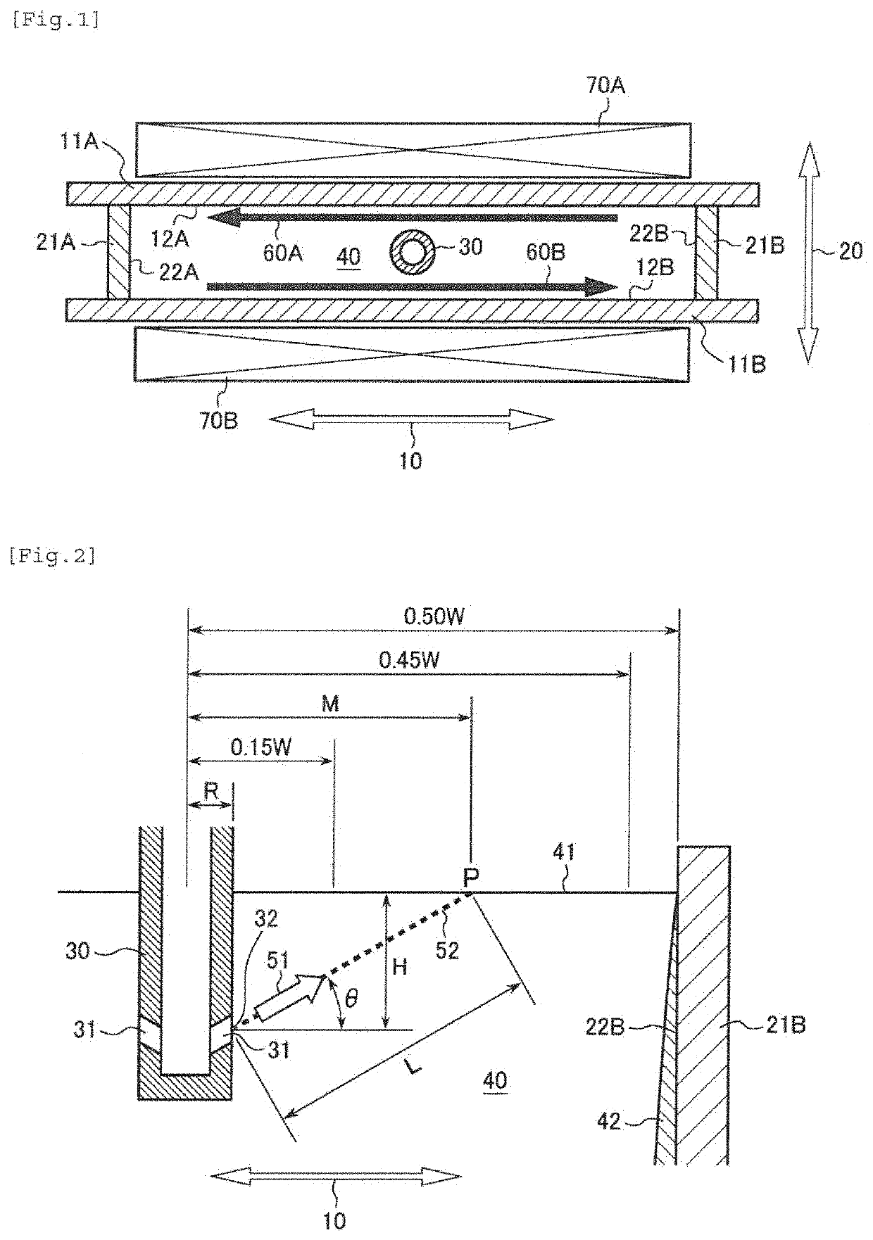
A continuous casting method includes discharging a molten steel from discharge ports of a submerged nozzle under conditions (A) and (B); and performing electro-magnetic stirrer (EMS) to cause flows in directions inverse to each other in the long edge direction on both long edge sides in the molten steel in a region having a depth providing a thickness of a solidification shell of from 5 to 10 mm at least at a center position in the long edge direction. (A) a discharge extended line from the discharge port of the submerged nozzle intersects a molten steel surface in the mold at a point P, and the position of the point P satisfies 0.15≤M / W≤0.45; and (B) a condition satisfying 0≤L−0.17Vi≤350, wherein the unit for L is mm, and Vi represents a discharge velocity (mm / s) of the molten steel at the outlet opening.

Description

TECHNICAL FIELD[0001]The present invention relates to a continuous casting method for steel utilizing electro-magnetic stirrer (EMS).BACKGROUND ART[0002]As a continuous casting method for steel, a method of injecting molten steel into a mold (casting mold) with a submerged nozzle having two discharge ports has been widely employed. The molten steel discharged from the submerged nozzle unavoidably contains bubbles, non-metallic particles, and the like mixed therein. Representative examples of the bubbles include argon gas bubbles. Argon is blown into the molten steel in the process of refining, such as VOD and AOD, used as a seal gas for a tundish, or intentionally added to the molten steel flow channel for preventing clogging of the nozzle, but is substantially not dissolved in the molten steel, and thus tend to mix in the mold as bubbles. The non-metallic particles mainly include a part of such materials as a slag for refining, a deoxidation product formed in the refining process, ...

Claims


Application Information

Patent Timeline
Patent Type & Authority Patents(United States)
IPC IPC(8): B22D11/115B22D11/20B22D11/10C22C38/54B22D41/50
CPCB22D11/115B22D11/20B22D11/10C22C38/54B22D41/50C22C38/18C22C38/02C22C38/04C22C38/42C22C38/44C22C38/46C22C38/48C22C38/50B22D11/186B22D11/18C22C38/22B22D11/00C22C38/00
Inventor EHARA, YASUHIROSAITO, SHUNMORITA, KAZUNARIMORIKAWA, HIROSHI
Owner NIPPON STEEL STAINLESS STEEL CORP
Learn More