Tethered eye cannula and method of use

a technology of eye cannula and eye cannula, which is applied in the field of cannulas, can solve the problems of difficult access to intraocular fluid space, difficult treatment of eyes, and inability to use needles, etc., and achieve the effect of reducing the force experienced

Active Publication Date: 2020-09-01
UNIV OF SOUTH FLORIDA
View PDF4 Cites 4 Cited by
  • Summary
  • Abstract
  • Description
  • Claims
  • Application Information

AI Technical Summary

Benefits of technology

[0020]An object of the invention is to provide a novel cannula design and method of implanting said cannula to reduce forces experienced on the insertion portion of the cannula when the cannula is tethered to a medical device.

Problems solved by technology

The treatment of eyes is typically a difficult medical task.
Intraocular fluid spaces on the other hand are difficult to access.
A fine gauge needle can be inserted for a short duration, but needles are not a viable option when long-term access is desired.
This approach is prone to cannula slippage from animal movement.
The technique disclosed therein used a non-bent cannula and required an additional “scleral anchor plate,” which may not work as well in animals with smaller eyes like rats.
Tethered eye cannulas impose additional mechanical forces that can cause the inserted end of the cannula to move within the eye causing damage to the eye.
This issue stems from the fact that a tethered cannula is secured at a second end and no longer able to simply move with the eye.
A straight tethered cannula does not work very well due to this issue.
Furthermore, where a definition or use of a term in a reference, which is incorporated by reference herein, is inconsistent or contrary to the definition of that term provided herein, the definition of that term provided herein applies and the definition of that term in the reference does not apply.

Method used


Image

  • Tethered eye cannula and method of use
  • Tethered eye cannula and method of use
  • Tethered eye cannula and method of use

Examples


Embodiment Construction

[0037]In the following detailed description of the preferred embodiments, reference is made to the accompanying drawings, which form a part thereof, and within which are shown by way of illustration specific embodiments by which the invention may be practiced. It is to be understood that other embodiments may be utilized and structural changes may be made without departing from the scope of the invention.

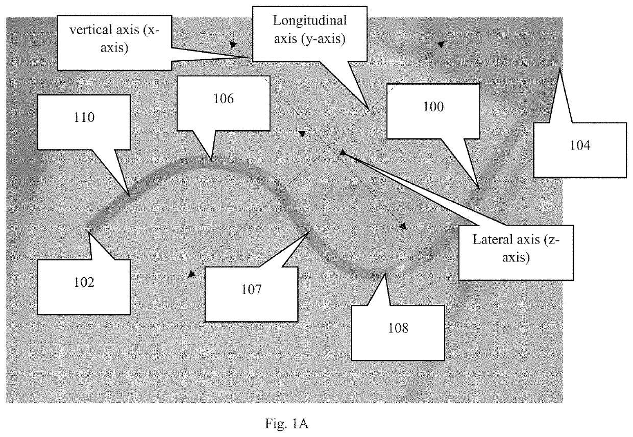
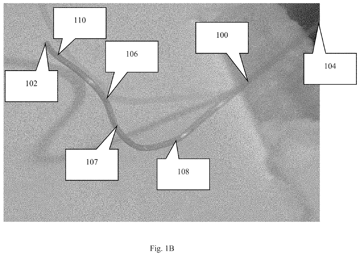
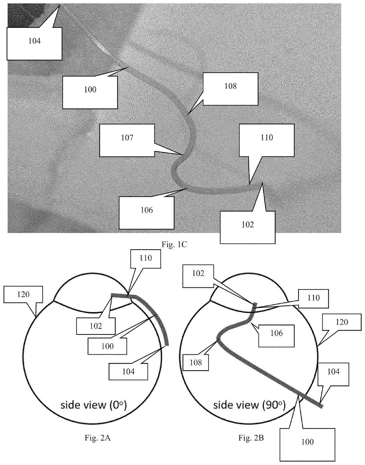
[0038]The invention addresses the problem of securing a tethered cannula within a subject's eye without the risk of the insertion portion of the cannula or the cannula tip inside the eye moving after being implanted. A cannula may be tethered to a device, such as a pressure measuring device or a fluid adjustment device, that is secured on or to the subject. A tethered cannula, in particular, is more susceptible to movement / dislodgement while implanted because the forces experienced by the cannula are constantly changing as the subject and the subject's eye move. A minor change in a ...


PUM


Abstract

A tethered cannula having at least two curved sections for implantation into an eye and a method for implanting the cannula in the eye. The cannula can withstand ever present and changing rotational forces from eye movement and mechanical forces from the movement of the subject. The cannula can be connected to implantable or tetherable devices that are too large, heavy, or obstructive to attach directly to the eye, such as an intraocular pressure sensor or infusion pump.

Description

CROSS-REFERENCE TO RELATED APPLICATIONS[0001]This nonprovisional application is a continuation of and claims priority to provisional application No. 62 / 407,825, entitled “METHOD OF IMPLANTING A TETHERED CANNULA IN THE EYE,” filed Oct. 13, 2016 by the same inventors.FEDERALLY SPONSORED RESEARCH OR DEVELOPMENT[0002]This invention was made with Government support under Grant No. R21EY023376 awarded by the National Institutes of Health. The government has certain rights in the invention.BACKGROUND OF THE INVENTION1. Field of the Invention[0003]This invention relates, generally, to cannulas. More specifically, it relates to a novel eye cannula shape and a method of implanting and securing a tethered cannula to the eye.2. Brief Description of the Prior Art[0004]The treatment of eyes is typically a difficult medical task. Ophthalmic drugs instilled in the eye are usually diluted by tears and cleared by tear ducts, and only a small fraction actually reaches the targeted tissues inside the e...

Claims


Application Information

Patent Timeline
Patent Type & Authority Patents(United States)
IPC IPC(8): A61F9/00A61B3/16A61B17/34
CPCA61B3/16A61B17/34A61F9/0017A61B2017/3482A61B2017/3458A61B17/3421A61B17/3468
Inventor PASSAGLIA, CHRISTOPHER LAWRENCEMALAVADE, SHARAD SURYAKANT
Owner UNIV OF SOUTH FLORIDA
Why Eureka
Try Eureka