Adjustable damping valve device

a damping valve and adjustable technology, applied in the direction of valve operating means/releasing devices, springs/dampers functional characteristics, shock absorbers, etc., can solve the problem of small dimensional error effect, and achieve the effect of promoting movement efficiency

Active Publication Date: 2020-09-01
ZF FRIEDRICHSHAFEN AG
View PDF14 Cites 2 Cited by
  • Summary
  • Abstract
  • Description
  • Claims
  • Application Information

AI Technical Summary

Benefits of technology

[0010]In order to minimize any manufacturing inaccuracies, the emergency operation armature is supported peripherally on a cover surface of the pre-stage valve body. The larger the contact circle between the emergency operation armature and the pre-stage valve body, the smaller the effects of dimensional errors.
[0013]The support surface preferably has a knife edge geometry. The knife edge geometry aims at a line contact between the emergency operation armature and the pre-stage valve body so that an angular error between the emergency operation armature and the pre-stage valve body can easily be compensated.
[0014]To promote the efficiency of movement of the emergency operation armature, the latter has a flow connection which connects two spaces of the damping valve device which are separated from one another by the emergency operation armature. Accordingly, no hydraulically closed spaces can be formed which could cause negative pressure or a backup pressure.

Problems solved by technology

The larger the contact circle between the emergency operation armature and the pre-stage valve body, the smaller the effects of dimensional errors.

Method used


Image

  • Adjustable damping valve device
  • Adjustable damping valve device

Examples


Embodiment Construction

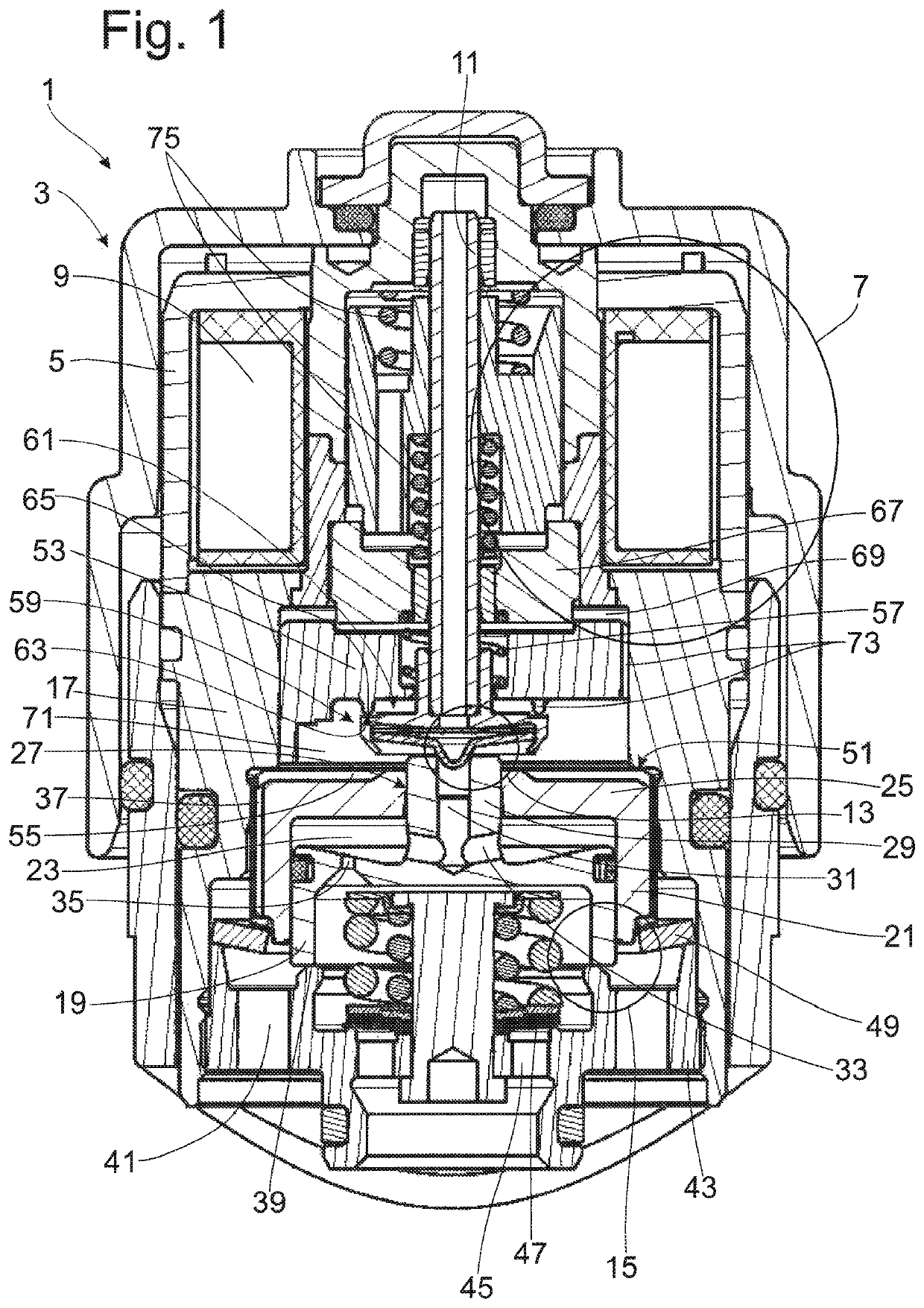
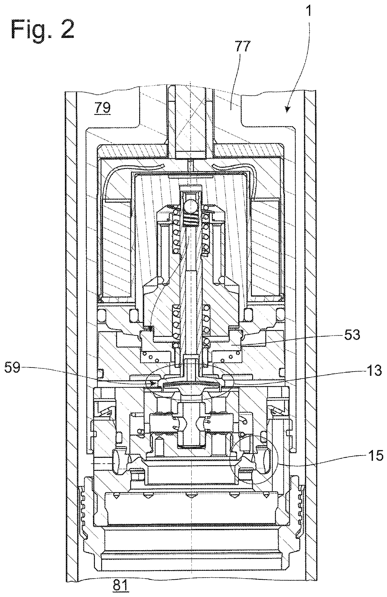
[0020]FIG. 1 shows a damping valve device 1 with a damping valve housing 3 for a vibration damper of any constructional type, this damping valve housing 3 being divided in two axially. In the present configuration, the damping valve device 1 is provided for external arrangement with respect to an outer cylinder of the vibration damper, but the construction principle can easily be adapted to a damping valve device, e.g., to a piston rod on a damping valve device. An actuator 7, known per se, which comprises a coil 9 acting on a pre-stage valve 13 via an armature 11 is arranged in a first damping valve housing portion 5. A main stage valve 15 which generates the damping force in the vibration damper is controlled with the pre-stage valve 13. The pre-stage valve 13 and the main stage valve 15 are arranged in the second damping valve housing portion 17 which has a tubular base shape without an intermediate wall.

[0021]The main stage valve 15 comprises a main stage valve body 19 which is ...


PUM


Abstract

An adjustable damping valve device for a vibration damper, includes a main stage valve which is controlled by a pre-stage valve with a pre-stage valve body, which pre-stage valve can be actuated by an electromagnetic actuator, wherein an emergency operation valve controls the main stage valve during emergency operation, wherein an emergency operation armature is preloaded on the pre-stage valve body of the pre-stage valve by an emergency operation spring so that the pre-stage valve forms the emergency operation valve.

Description

PRIORITY CLAIM[0001]This is a U.S. national stage of application No. PCT / EP2015 / 079697, filed on Dec. 15, 2015. Priority is claimed on the following application(s): Country: Germany, Application No.: 10 2015 200 348.5, filed: Jan. 13, 2015, the content of which is / are incorporated herein by reference in its entirety.FIELD OF THE INVENTION[0002]The invention is directed to an adjustable damping valve device with an emergency operation function.BACKGROUND OF THE INVENTION[0003]An adjustable damping valve device comprising a pre-stage valve and a main stage valve is known from U.S. Pat. No. 9,297,437. Further, an emergency operation valve which occupies an emergency operation position during an outage of the power supply for an actuator of the damping valve device is connected in series with the pre-stage valve. At least one pressure relief valve which opens in the event of overpressure in a control space of the damping valve device and accordingly determines a maximum damping force se...

Claims


Application Information

Patent Timeline
Patent Type & Authority Patents(United States)
IPC IPC(8): F16F9/46F16K31/06F16F9/34
CPCF16F9/34F16K31/0679F16F9/46F16F9/464F16F2230/24F16F2228/066F16F9/3207
Inventor MANGER, THOMASRUHMANN, LUKASSCHMITT, STEFAN
Owner ZF FRIEDRICHSHAFEN AG
Why Eureka
Try Eureka