Medical imaging equipment and a measuring method for detecting the position of a conveying device of the medical imaging equipment

a technology of medical imaging equipment and conveying device, which is applied in the direction of counting objects on conveyors, instruments, applications, etc., can solve the problems of high accuracy exposure to treatment and/or examination radiation, and inaccuracy of conveying device detected position

Inactive Publication Date: 2014-04-08
SIEMENS HEALTHCARE GMBH
View PDF9 Cites 3 Cited by
  • Summary
  • Abstract
  • Description
  • Claims
  • Application Information

AI Technical Summary

Benefits of technology

[0010]It is proposed that the position-detecting device comprises at least one semi-transparent reflector element. The medical imaging equipment is formed in particular by a magnetic resonance tomography apparatus, a computerized tomography apparatus and / or a PET apparatus and comprises a receiving region in which an imaging medical examination can take place on an object for examination, in particular on a patient. In this connection a semi-transparent reflector element should in particular be taken to mean an element by means of which a first radiation fraction of incident radiation, in particular the incident position-measuring radiation, may be reflected and a further radiation fraction of the incident radiation may be transmitted by the semi-transparent reflector element. The semi-transparent reflector element can, by way of example, be formed by a semi-transparent mirror and / or in a particularly compact manner by a semi-transparent foil and / or a semi-transparent coating which is applied to a detector surface. The position-detecting device can, moreover, comprise a plurality of detector elements which are particularly advantageously arranged within a detector array. A distance from the transmitting element and / or detector element to the conveying device, in particular a reference point of the conveying device, may advantageously be precisely detected by way of the embodiment according to the invention in that radiation fractions having a different path length between transmitting element and detector element may be detected. Following each impingement of the position-measuring radiation on the semi-transparent reflector element the radiation fraction transmitting the semi-transparent reflector element may be detected and the radiation fraction reflected by the semi-transparent reflector element has to be transmitted again through at least twice the path length between the semi-transparent reflector element and a further reflector element before it strikes the semi-transparent reflector element again.
[0011]It is also proposed that the semi-transparent reflector element is arranged upstream of the detector element along a radiation path of the position-measuring radiation. The semi-transparent reflector element is in the process arranged inside the position-detecting device in such a way that a length of the single radiation path from the transmitting element to the semi-transparent reflector element substantially matches a length of the single radiation path from the transmitting element to the detector element. A radiation fraction that penetrates the semi-transparent reflector element can be directly detected by the detector element and, moreover, an advantageous multiplicity of a length of a distance that is to be detected may be achieved, and therewith minimization of an inaccuracy in the distance to be detected.
[0020]It is proposed that a first radiation fraction of the position-measuring radiation is transmitted along a radiation path between the emission step and the detection step on at least one semi-transparent reflector element and that a second radiation fraction of the position-measuring radiation is reflected at the semi-transparent reflector element. One radiation fraction can therefore be detected by the detector element and a further radiation fraction can be available to pass through a further reflection path. A distance from the transmitting element and / or the detector element to the conveying device, in particular a reference point of the conveying device, may advantageously be precisely detected hereby in that the distance may be detected with a different level of multiplicity of a path length of the distance, and therefore a method-dependent inaccuracy when determining the distance may be minimized.
[0021]It is also proposed that the position-measuring radiation is reflected at least one further reflector element, whereby a high multiplicity of a path length of the distance to be detected and / or a path length covered by the conveying device may be achieved and the accuracy of the position to be detected and / or a distance to be detected may be increased in this way.
[0025]If a signal characteristic of the position-measuring radiation is at least partially detected to control triggering, a trigger threshold for activating a detection process may advantageously be adjusted at, by way of example, a reducing signal strength. Signal components with a high number of reflections, and therefore a particularly low signal strength, may in particular be advantageously detected in this way.
[0029]It is also proposed that the position-measuring radiation is emitted with a beam direction which encloses an angle of greater than 0° to a surface normal of a reflective surface of a reflector element. The angle is preferably dependent on a maximum number of reflections of the position-measuring radiation along a radiation path from the transmitting element to the detector element. Furthermore, the angle can be dependent on a width of the reflective surface and / or a width of the detection area, so the reflective surface and / or the detection area may be effectively used. Inaccuracies in a measuring method may therefore be detected particularly exactly and a distance precisely determined therefore.

Problems solved by technology

However, there is a great inaccuracy in the detected position of the conveying device with this method.
However, this method has the drawback that owing to an elasticity and / or a stretching of a material of the thread take-ups the detected position of the conveying device is highly inaccurate.
However, this method has the drawback that these sensors and / or controllers are arranged at least partially within the receiving region and are therefore exposed to treatment and / or examination radiation.
This can undesirably impair both treatment and position detection.
Conventional measuring methods, such as a time of flight method by way of example, are very imprecise in terms of position detection, however.
Furthermore, the laser source and / or the detector element are arranged on the movable conveying device and are therefore exposed to examination radiation.

Method used


Image

  • Medical imaging equipment and a measuring method for detecting the position of a conveying device of the medical imaging equipment
  • Medical imaging equipment and a measuring method for detecting the position of a conveying device of the medical imaging equipment
  • Medical imaging equipment and a measuring method for detecting the position of a conveying device of the medical imaging equipment

Examples


Embodiment Construction

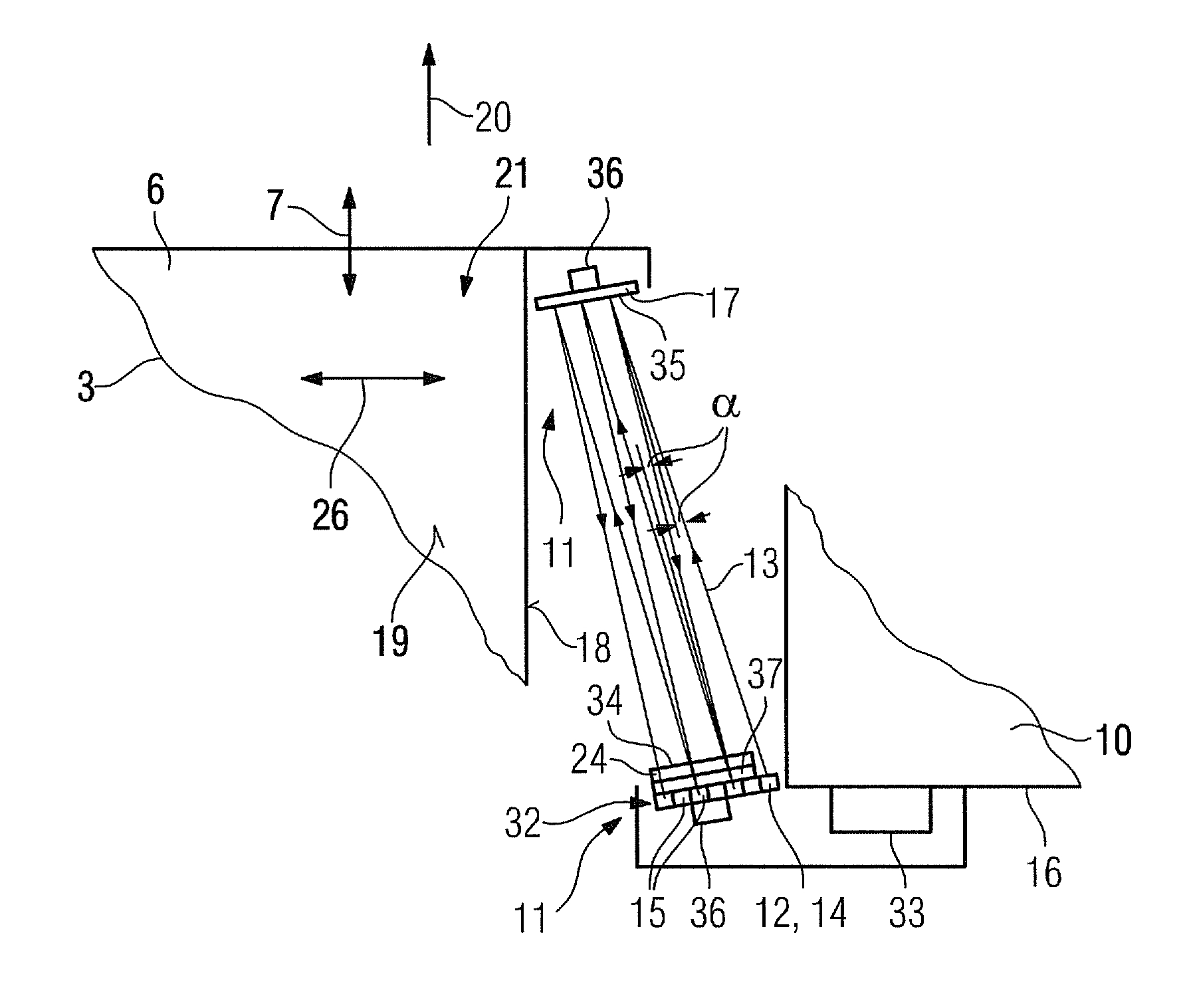
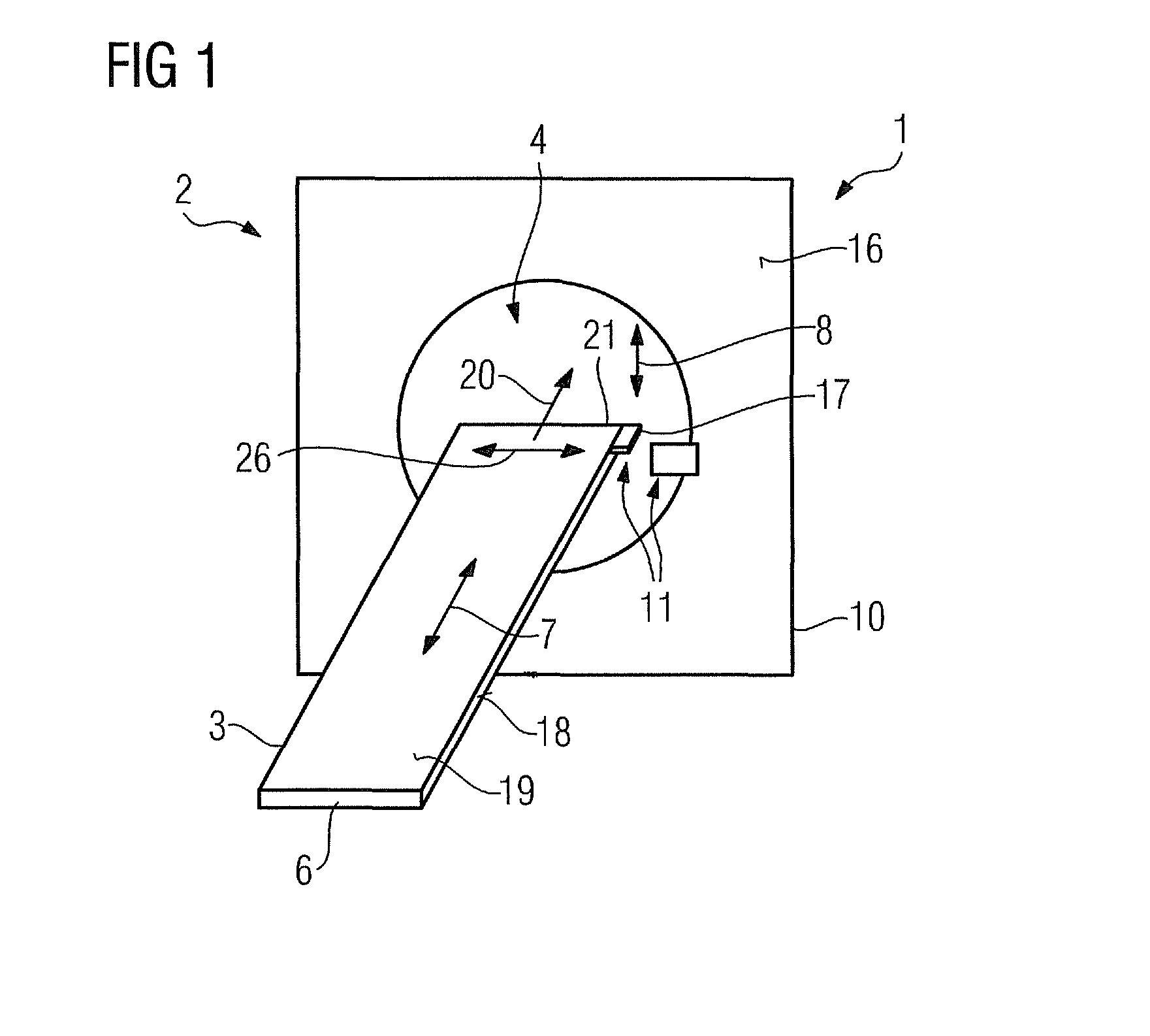
[0039]FIG. 1 shows inventive medical imaging equipment 1 which is formed by a magnetic resonance tomography apparatus 2. The magnetic resonance tomography apparatus 2 comprises a main magnet (not shown in detail) for producing a strong and constant magnetic field. The magnetic resonance tomography apparatus 2 also comprises gradient coils (not shown in detail), which are provided to produce a linear gradient field, and high frequency coils (not shown in detail). The magnetic resonance tomography apparatus 2 also comprises a receiving region 4 for receiving an object for examination and / or a patient for an imaging examination. In an alternative embodiment the medical imaging equipment 1 can also be formed by a computerized tomography apparatus and / or a PET apparatus.

[0040]The medical imaging equipment 1 also comprises a conveying device 3, which includes a patient couch 6 and is movably arranged in a z-direction 7. The z-direction 7 runs parallel to a surface normal of a receiving op...


PUM


Abstract

A medical imaging equipment has a conveying device that can be moved at least partially in at least one direction. A position-detecting device has at least one transmitting element which detects a position of the conveying device and emits position-measuring radiation. The position-detecting device has at least one detector element. The position-detecting device has at least one semi-transparent reflector element.

Description

CROSS REFERENCE TO RELATED APPLICATIONS[0001]This application claims priority of German application No. 10 2009 054 916.1 filed Dec. 18, 2009 and German application No. 10 2010 020 923.6 filed May 1, 2010, both of the applications are incorporated by reference herein in their entirety.FIELD OF THE INVENTION[0002]The present invention relates to medical imaging equipment having a conveying device that can be moved at least partially in at least one direction, and a position-detecting device, comprising at least one transmitting element which for detecting the position of the conveying device emits position-measuring radiation, and at least one detector element.BACKGROUND OF THE INVENTION[0003]Medical imaging equipment having a conveying device that is movable in at least one direction is already known. The medical imaging equipment, by way of example a magnetic resonance tomography apparatus, a computerized tomography apparatus and / or a PET apparatus, is very accurate and this requir...

Claims


Application Information

Patent Timeline
Patent Type & Authority Patents(United States)
IPC IPC(8): A47B13/00G06M7/00
CPCA61B6/0407A61B6/547
Inventor GROSS, PATRICK
Owner SIEMENS HEALTHCARE GMBH
Why Eureka
Try Eureka