Instrument coupling interfaces and related methods

a coupling interface and instrument technology, applied in the field of coupling interfaces, can solve the problems of inability to obtain a repeatable known position and orientation between the two mated objects, etc., to achieve the effect of minimizing or eliminating the inaccuracy of navigation

Active Publication Date: 2020-08-04
MEDOS INT SARL
View PDF114 Cites 2 Cited by
  • Summary
  • Abstract
  • Description
  • Claims
  • Application Information

AI Technical Summary

Benefits of technology

[0006]Instrument coupling interfaces and related methods are disclosed herein, e.g., for coupling a surgical instrument to a navigation array or other component. An exemplary coupling can include a first coupling interface associated with a first object, such as a surgical instrument, and a second coupling interface associated with a second object, such as a navigation array. The coupling interfaces can be configured to ensure that, when mated, the first and second objects are disposed in a known position and orientation relative to one another and blocked from relative movement in all six degrees of freedom. The interfaces can have a geometry that is not overdetermined, minimizing or eliminating navigation inaccuracy associated with system tolerances. An exemplary coupling can include counterpart centering features for blocking X-axis translation and Y-axis translation, counterpart rotation stops for blocking Z-axis rotation, counterpart reference planes for blocking X-axis rotation, Y-axis rotation, and Z-axis translation in a first direction, and a locking element for blocking Z-axis translation in a second, opposite direction.

Problems solved by technology

Such a geometry can introduce error when tolerances are suboptimal.
In such cases, when mated to a first object A, different second objects may contact different ones of the eight surfaces, such that it is not possible to obtain a repeatable known position and orientation between the two mated objects.
While a V-groove geometry is shown, dovetail and other type connections can also be overdetermined and suffer from similar inaccuracies.
When these couplings are used, the tolerances must be tightly controlled, which can increase manufacturing cost and decrease manufacturing yield, or a certain level of inaccuracy must be accepted.
Cone or V-shaped surfaces can be very sensitive to tolerances which can lead to varying gap size when the mating surfaces are brought together.
Damage or excessive wear to the contact surfaces 210 can compromise navigation accuracy.
Damage or excessive wear to the contact surfaces 212 can compromise navigation accuracy.

Method used


Image

  • Instrument coupling interfaces and related methods
  • Instrument coupling interfaces and related methods
  • Instrument coupling interfaces and related methods

Examples


Embodiment Construction

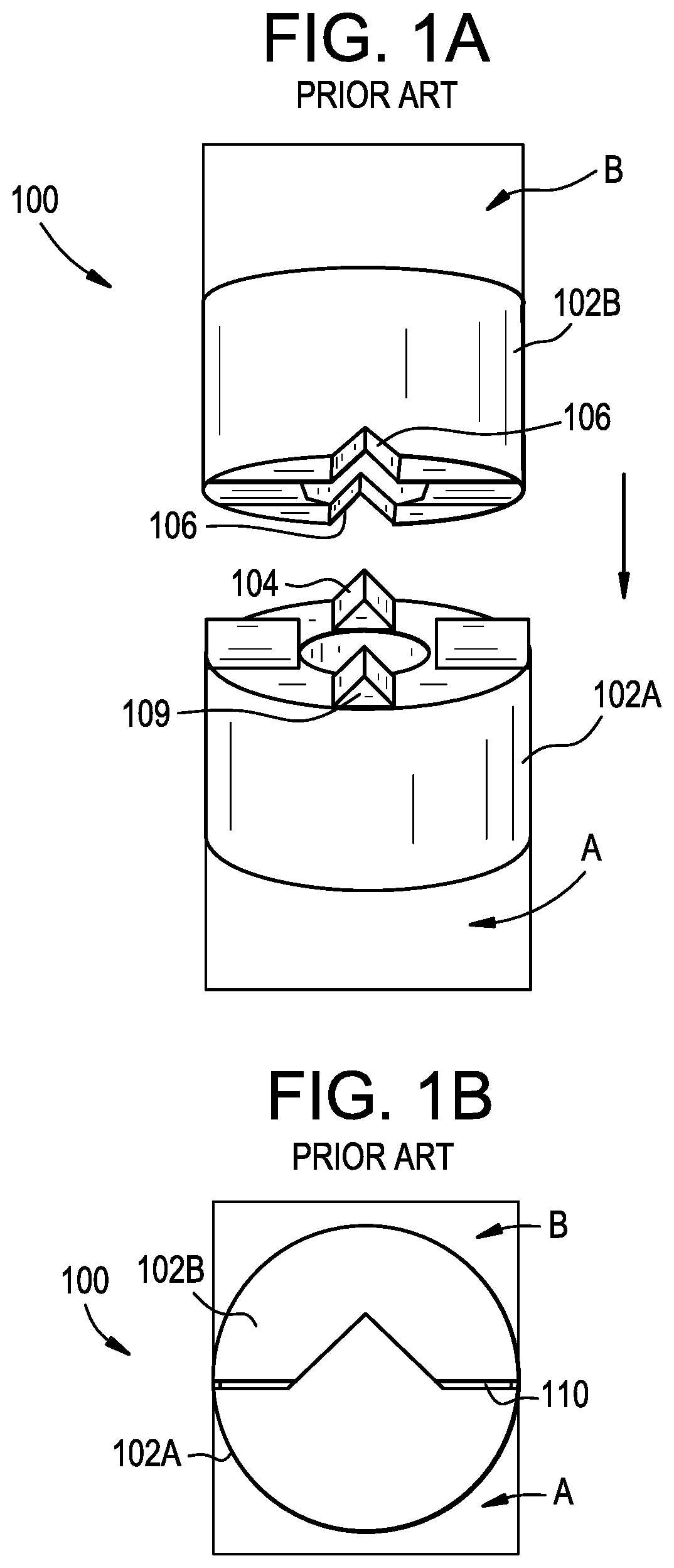
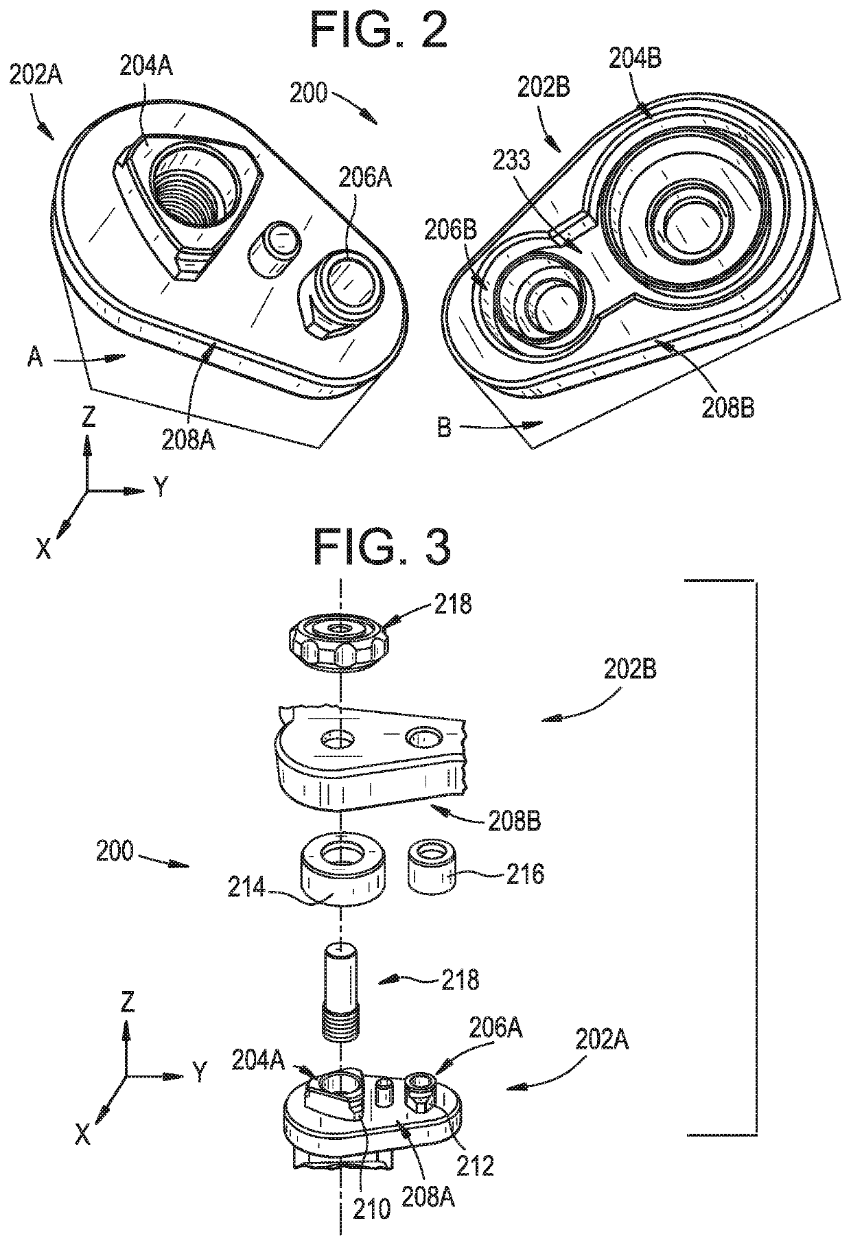
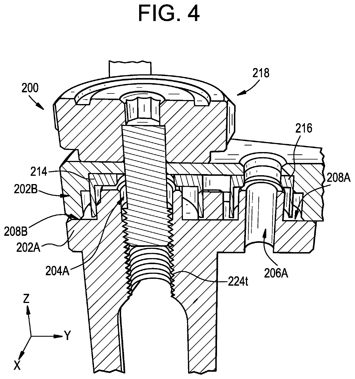
[0034]Instrument coupling interfaces and related methods are disclosed herein, e.g., for coupling a surgical instrument to a navigation array or other component. An exemplary coupling can include a first coupling interface associated with a first object, such as a surgical instrument, and a second coupling interface associated with a second object, such as a navigation array. The coupling interfaces can be configured to ensure that, when mated, the first and second objects are disposed in a known position and orientation relative to one another and blocked from relative movement in all six degrees of freedom. The interfaces can have a geometry that is not overdetermined, minimizing or eliminating navigation inaccuracy associated with system tolerances. An exemplary coupling can include counterpart centering features for blocking X-axis translation and Y-axis translation, counterpart rotation stops for blocking Z-axis rotation, counterpart reference planes for blocking X-axis rotatio...


PUM


Abstract

Instruments can include coupling interfaces that can b used, for example, for coupling a surgical instrument to a navigation array or other component. An exemplary coupling can include a first coupling interface associated with a first object, such as a surgical instrument, and a second coupling interface associated with a second object, such as a navigation array. The coupling interfaces can be configured to ensure that, when mated, the first and second objects are disposed in a known position and orientation relative to one another and blocked from relative movement in all six degrees of freedom. The interfaces can have a geometry that is not overdetermined, minimizing or eliminating navigation inaccuracy associated with system tolerances. An exemplary coupling can include counterpart centering features for blocking X-axis translation and Y-axis translation, counterpart rotation stops for blocking Z-axis rotation, counterpart reference planes for blocking X-axis rotation, Y-axis rotation, and Z-axis translation in a first direction, and a locking element for blocking Z-axis translation in a second, opposite direction.

Description

FIELD[0001]Instrument coupling interfaces and related methods are disclosed herein, e.g., for coupling a surgical instrument to a navigation array or other component.BACKGROUND[0002]Navigation or tracking of instruments during surgical procedures has become increasingly popular. Surgical navigation can help surgeons avoid delicate neural or vascular structures when moving instruments within a patient. In spinal surgery, for example, a surgical navigation system can be used during disc removal, bone drilling, implant insertion, e.g., screw and / or cage insertion, and other steps of the surgery. Use of surgical navigation systems can also reduce the amount of X-ray exposure to which the patient and operating room staff are exposed.[0003]A typical navigation system includes an array of markers attached to a surgical instrument, an imaging system that captures images of the surgical field, and a controller that detects the markers in the captured images and tracks movement of the markers...

Claims


Application Information

Patent Timeline
Patent Type & Authority Patents(United States)
IPC IPC(8): F16B7/18A61B17/00
CPCF16B7/18A61B2017/00477Y10T403/7069Y10T403/1624A61B2090/3983A61B90/39
Inventor PONZER, RAINERLINDENMANN, PHILIPPE
Owner MEDOS INT SARL
Why Eureka
Try Eureka