Check patentability & draft patents in minutes with Patsnap Eureka AI!

Polarisation-independent, optical multiplexing and demultiplexing systems based on ferroelectric liquid crystal phase modulators for spatial mode division multiplexing and demultiplexing

a phase modulator and ferroelectric liquid crystal technology, applied in optics, instruments, electrical equipment, etc., can solve the problems of relatively complex and bulky techniques

Active Publication Date: 2020-09-01
CAMBRIDGE ENTERPRISE LTD
View PDF7 Cites 0 Cited by
  • Summary
  • Abstract
  • Description
  • Claims
  • Application Information

AI Technical Summary

Benefits of technology

[0007]In embodiments employing a polarisation-independent, controllably reconfigurable phase modulator enables efficient use of an available optical transmission system, and also facilitates controllable optical spatial mode dependent routing. Moreover this can be achieved with a compact optical design since there is no need to split different (orthogonal) polarisation components into separate beams—they can be processed together in a single beam (per mode).
[0012]The skilled person will appreciate that depending upon the optical arrangement either a transmissive or a reflective ferroelectric crystal SLM may be employed. A reflective FLC SLM may be an LCOS (liquid crystal on silicon) device; this facilitates driving where the device comprises many pixels. In embodiments, however, the FLC SLM may comprise a relatively low number of pixels, for example ≤16 or ≤8, in embodiments four pixels.

Problems solved by technology

However this paper describes a lab-based proof of principle for mode division multiplexing and is not concerned with the solution of practical “in the field” problems.
However this is technique relatively complex and bulky and improvements are desirable.

Method used


Image

  • Polarisation-independent, optical multiplexing and demultiplexing systems based on ferroelectric liquid crystal phase modulators for spatial mode division multiplexing and demultiplexing
  • Polarisation-independent, optical multiplexing and demultiplexing systems based on ferroelectric liquid crystal phase modulators for spatial mode division multiplexing and demultiplexing
  • Polarisation-independent, optical multiplexing and demultiplexing systems based on ferroelectric liquid crystal phase modulators for spatial mode division multiplexing and demultiplexing

Examples


Embodiment Construction

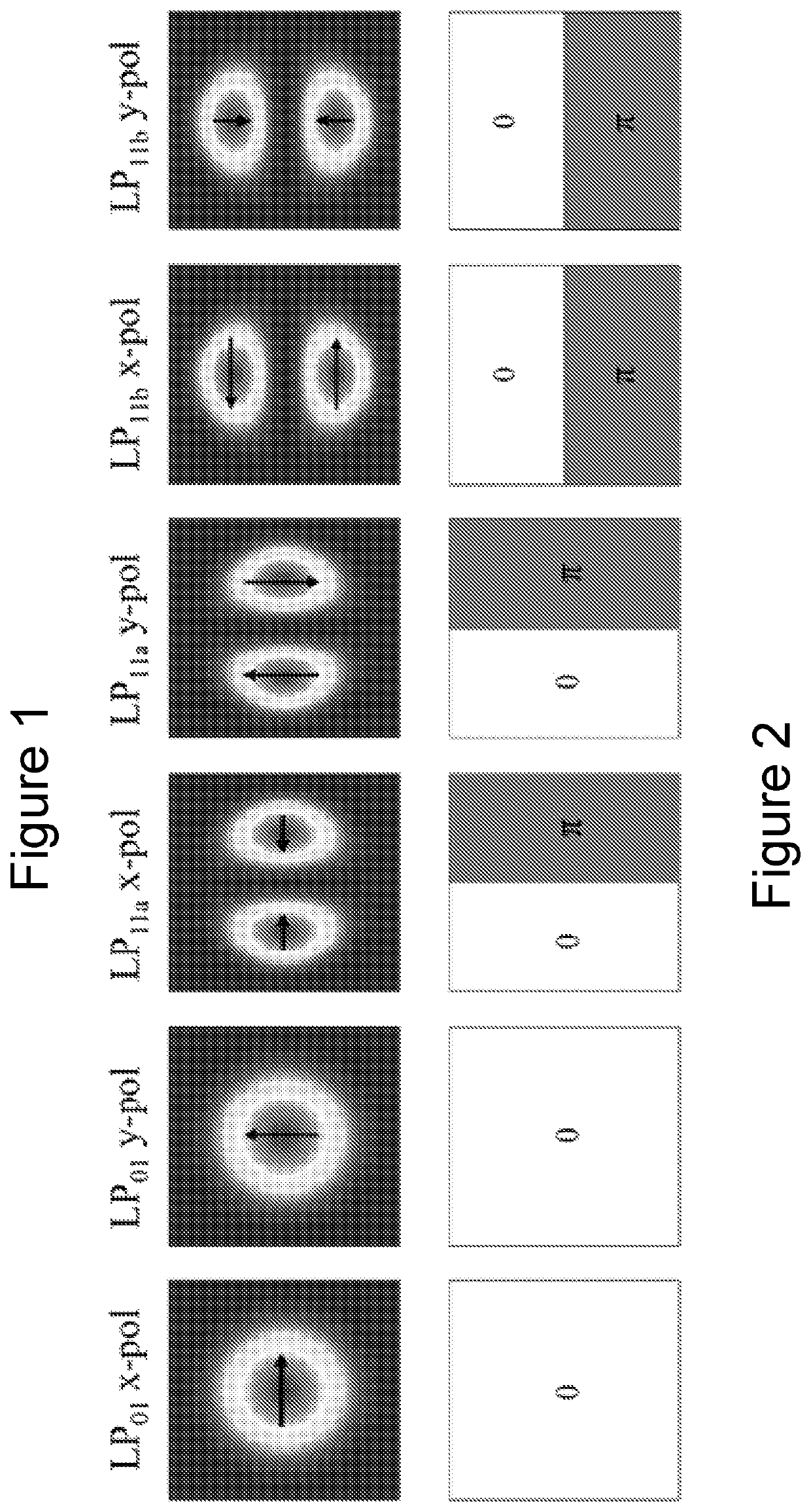
[0033]Referring to FIGS. 1 and 2, these shows transverse intensity and phase profiles of different LP modes of an optical fibre. In FIG. 1 the arrows in the intensity profiles indicate that the primary direction of the field in each profile, which ultimately determines the polarisation direction of the mode. Typical telecommunication lasers generate an LP01 mode beam and thus when mode division multiplexing is employed higher order LP modes, such as LP11 modes, are excited from the LP01 mode before being multiplexed into the MMF (multimode fibre). Conversion from a lower order to a higher order mode can be achieved by imposing a phase profile as shown in FIG. 2. The higher order mode can be observed in the far field beyond the phase mask, but can be brought nearer to the phase mask by employing a demagnifying optical system between the phase mask and the multimode fibre (diverging the light forming the higher LP mode).

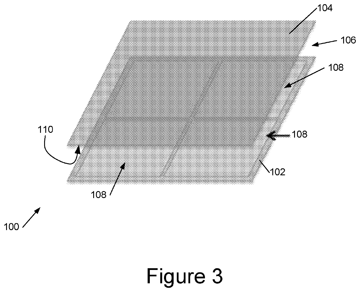
[0034]FIG. 3 shows an embodiment of a polarisation-independent, c...


PUM

PropertyMeasurementUnit
switching angleaaaaaaaaaa

Abstract

We describe a multimode reconfigurable optical spatial mode multiplexing system having first and second first and second input beams and a beam combiner to combine these into an optical output. At least one of the paths comprises a polarisation-independent reconfigurable phase modulator to impose a controllable phase profile on an input beam in an input beam phase modulating optical path, to controllably convert a spatial mode order of the input beam from a lower to a higher order spatial mode. The system also has a control input to control the phase modulator to configure the phase profile for the mode conversion. The input beams are combined into a multiple spatial mode combined beam output independent of a polarisation of the input beams. The number of spatial modes of the combined beam can be more than a number of spatial modes in either of the first and second input beams separately.

Description

FIELD OF INVENTION[0001]This invention relates to methods and apparatus for reconfigurable optical spatial mode multiplexing / demultiplexing.BACKGROUND TO THE INVENTION[0002]There are numerous advantages to using single mode fibres in optical communication systems, but as the global demand for bandwidth increases new ways to encode data are sought. Thus amplitude, phase, wavelength and polarisation are currently employed for data encoding and, despite the advantages of single mode fibre, potentially optical spatial mode division multiplexing using multimode fibre provides a potential further method of increasing the data capacity in future telecommunication systems.[0003]In a single mode fibre (SMF) communication system only light of the fundamental linear polarised (LP) mode, that is the LP01 mode is able to propagate, broadly speaking because the fibre has a small core diameter. Multimode fibre (MMF) has a larger core diameter and multiple light beams of different cross-sectional s...

Claims


Application Information

Patent Timeline
Patent Type & Authority Patents(United States)
IPC IPC(8): G02F1/141
CPCG02F1/141G02F2203/06G02F2203/12H04J14/021
Inventor CHU, DAPINGYANG, HAINING
Owner CAMBRIDGE ENTERPRISE LTD
Features
  • R&D
  • Intellectual Property
  • Life Sciences
  • Materials
  • Tech Scout
  • Unparalleled Data Quality
  • Higher Quality Content
  • 60% Fewer Hallucinations
Learn More