Mo-doped Co2Z-type ferrite composite material for use ultra-high frequency antennas

a composite material and ultra-high frequency technology, applied in the direction of magnetism of inorganic materials, magnetic materials, magnetic bodies, etc., can solve the problems of not meeting the need for the design of a practical antenna, difficult to develop ferrite materials for such high frequency applications, and known ferrite materials exhibit relatively high magnetic losses at high frequencies. , to achieve the effect of low dielectric and magnetic losses, high frequency range, and permeability and permittivity

Active Publication Date: 2020-09-08
ROGERS CORP
View PDF23 Cites 7 Cited by
  • Summary
  • Abstract
  • Description
  • Claims
  • Application Information

AI Technical Summary

Benefits of technology

[0004]The invention relates to a hexaferrite composition useful as a magnetic material in electrical devices operating in the high frequency range. The hexaferrite composition comprises barium and / or strontium, molybdenum, cobalt, and iron and has a Z-type hexaferrite phase. The hexaferrite can be stoichiometric or non-stoichiometric. With substitutions of barium, strontium, and molybdenum as described herein, it is possible to provide magnetodielectric hexaferrite compositions of tunable permeability and permittivity and low dielectric and magnetic losses over high frequency ranges. The hexaferrite compositions can also be cost-effective for the mass production of devices such as microwave antenna substrates and in spintronics applications, such as giant magnetoresistant (GMR) devices. The invention also relates to methods of making the hexaferrite composition and articles, devices, or parts that comprise the hexaferrite composition.

Problems solved by technology

It has, however, been challenging to develop ferrite materials for use in such high frequency applications.
Known ferrite materials exhibit relatively high magnetic losses at high frequencies, which have not met the need for the design of a practical antenna.
Such materials enable miniaturization, while concomitantly maintaining or enhancing antenna gain and bandwidth.
However, these ferrites exhibit relatively low cutoff frequencies that prevent their use above 0.3 GHz.
However, it is very challenging to obtain low magnetic and dielectric losses and high permeability of the dielectric substrates.

Method used


Image

  • Mo-doped Co<sub>2</sub>Z-type ferrite composite material for use ultra-high frequency antennas
  • Mo-doped Co<sub>2</sub>Z-type ferrite composite material for use ultra-high frequency antennas
  • Mo-doped Co<sub>2</sub>Z-type ferrite composite material for use ultra-high frequency antennas

Examples


example 1

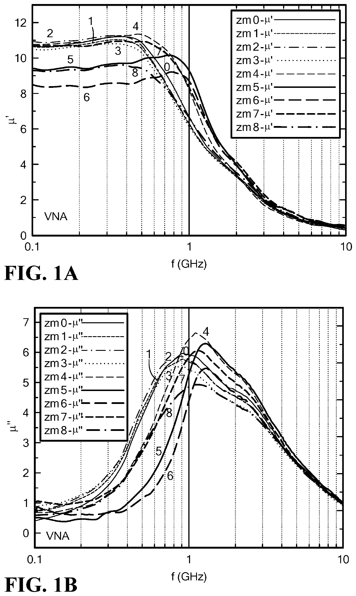
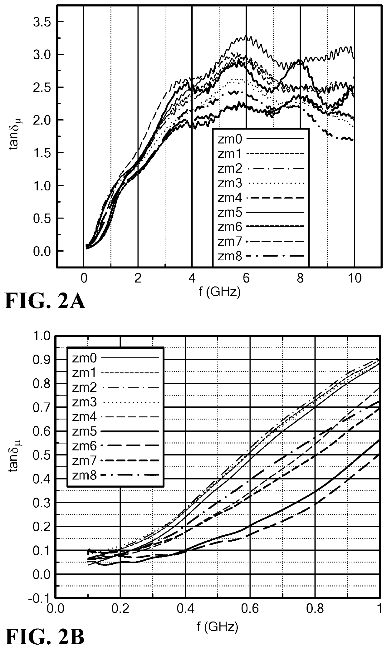
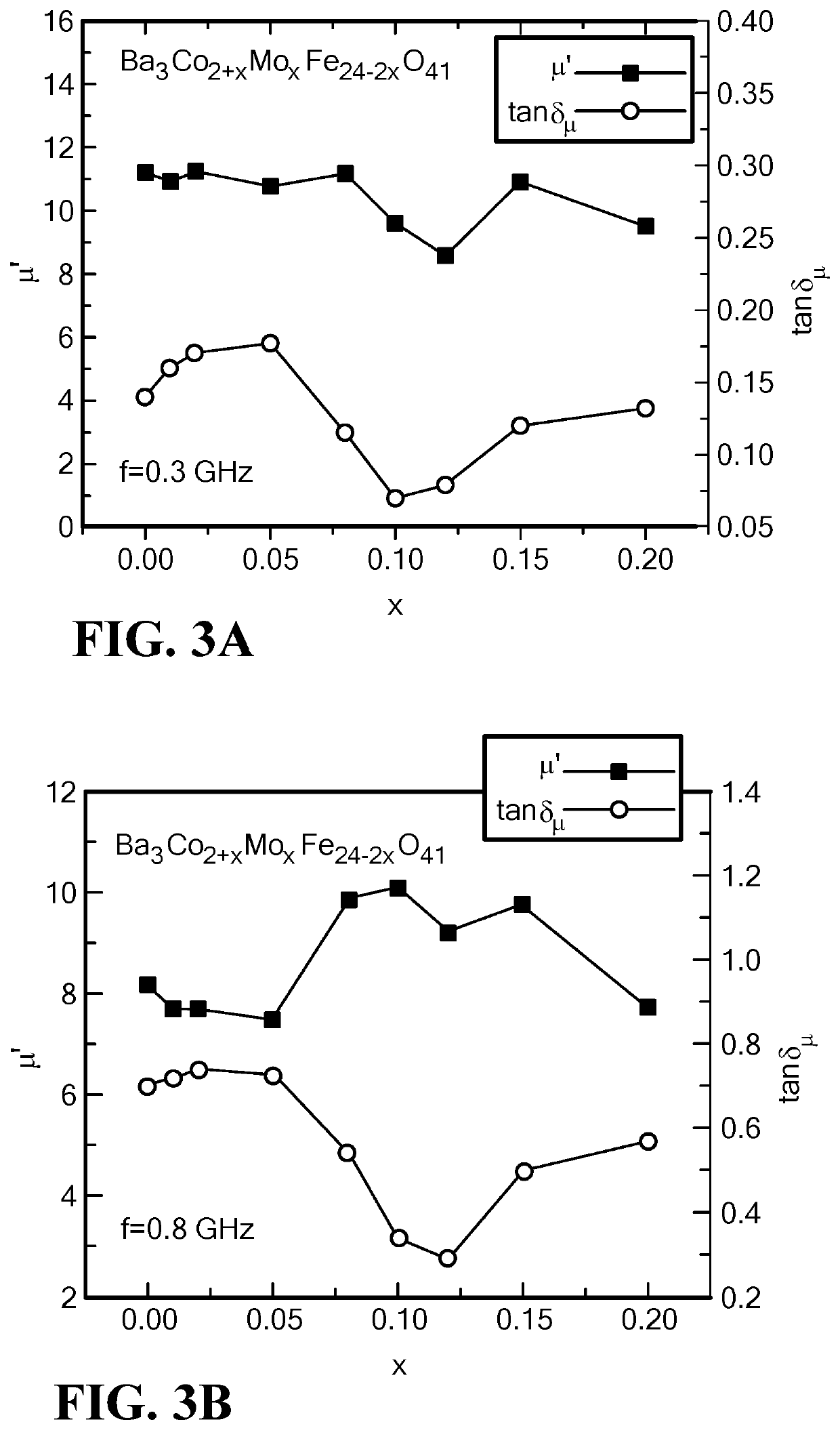
[0150]Polycrystalline Co2Z hexaferrites, having the composition Ba3Co2+xMoxFe24-2xO41, where x=0, 0.01, 0.02, 0.05, 0.08, 0.10, 0.12, 0.15 and 0.20, were prepared by a two-step ceramic process. Starting materials of BaCO3, MoO2, Co3O4, and Fe2O3 were calcined in air for 6 hours at 1000° C., and then crushed and ball milled. The mixture, comprising 90 v % ferrite fine powders and 10 v % polyvinyl alcohol (PVA) binder, was pressed into a toroid with an outer diameter of 7 mm, inner diameter of 3 mm, and width of about 2 mm. This sample size is adequate for microwave measurements. Since oxygen atmosphere can help decrease the dielectric loss, the hexaferrite samples were sintered at 1200 to 1280° C. for 4 to 20 hours in oxygen as a final process step. (An annealing step, typically used to establish oxygen stoichiometry, was not used due to the long, 20-hour, heat treatment step.) Eight samples, listed with a corresponding identifying code ZM0 to ZM8, correspond to the inclusion of Mo i...

example 2

[0174]Polycrystalline hexaferrites having a non-stoichiometric composition with the formula (BazSr(3-z))Co(2+x)MoxFe(y-2x)O41 were produced. Table 5 lists the non-stoichiometric formulas for several samples that were prepared and tested.

[0175]

TABLE 5Formula design (non-stoichiometric formula)CodeFormulaMo content, xZSF1Ba3Co(2+x)Fe(21.6-2x)MoxO41x = 0.12ZSF2Ba3Co(2+x)Fe(22.4-2x)MoxO41x = 0.12ZSF3Ba1.5Sr1.5Co(2+x)Fe(21.6-2x)MoxO41x = 0.12ZSF4Ba1.5Sr1.5Co(2+x)Fe(22.4-2x)MoxO41x = 0.12

[0176]The fabrication process began with the following raw materials and their purities: BaCO3 (99.95%), SrCO3 (99.95%), Co3O4 (99.7%), MoO2 (99%), and Fe2O3 (99.95%). The ratio of each was selected to be consistent with the targeted nominal compositions. For example, the hexaferrite phase precursor compounds can comprise 0 to 0.96 wt. % MoO2, 22.10-22.18 wt. % BaCO3, 6.02-6.59 wt. % Co3O4, and 70.35-71.8 wt. % Fe2O3.

[0177]The materials were mixed with reagent alcohol as a solvent and ground in an agate j...

example 3

[0189]Polycrystalline Co2Z hexaferrites, having the composition Sr3Co2+xMoxFe24-2xO41, where x=0, 0.02, 0.05, 0.08, 0.10, 0.12, 0.15 and 0.20, were prepared by the two-step ceramic process described above in Example 1, using as starting materials SrCO3, MoO2, Co3O4, and Fe2O3.

[0190]Results

1. Magnetic Permeability Spectra and Magnetic Loss

[0191]The permeability spectra were measured over frequencies of 0.1 to 10.0 GHz. The permeability exhibits a decrease from 3.8 to 3.3 at low frequency (0.1 GHz) with Mo content, except for a Mo content of x=0.10, as seen in FIG. 16. The Mo content gives rise to a shift of the loss tangent peak to higher frequencies above 5.0 GHz, as seen in FIG. 17. The Mo content x=0.10 results in a minimum loss tangent at the frequency range from 0.4 to 1.5 GHz, also seen in FIG. 17. That is, the loss tangent for x=0.20 is ˜0.1 at 0.4 GHz and 0.4 at 1.5 GHz, which is the lowest loss among the Mo-doped SrCo2Z ferrites.

[0192]FIG. 18 illustrates the results of perme...


PUM

PropertyMeasurementUnit
frequencyaaaaaaaaaa
frequencyaaaaaaaaaa
frequencyaaaaaaaaaa

Abstract

A Co2Z hexaferrite composition is provided containing molybdenum and one or both of barium and strontium, having the formula (Ba2Sr(3-Z)Co(2+X))MoxFe(y-2x)O41 where x=0.01 to 0.20; y=20 to 24; and z=0 to 3. The composition can exhibit high permeabilities and equal or substantially equal values of permeability and permittivity while retaining low magnetic and dielectric loss tangents and loss factors. The composition is suitable for high frequency applications such as ultrahigh frequency and microwave antennas and other devices.

Description

CROSS REFERENCE TO RELATED APPLICATIONS[0001]This application is a National Stage application of PCT / US16 / 015888, filed Feb. 1, 2016, which claims the benefit of U.S. Provisional Application No. 62 / 110,025, filed Jan. 30, 2015, both of which are incorporated by reference in their entirety herein.BACKGROUND[0002]Improved performance and miniaturization are needed to meet the ever-increasing demands of devices used in ultrahigh frequency (UHF), L-band, and S-band applications, which are of particular interest in a variety of commercial and defense related industries. As a critical component in radar and modern wireless communication systems, antenna elements with compact size are constantly being developed. It has, however, been challenging to develop ferrite materials for use in such high frequency applications. Known ferrite materials exhibit relatively high magnetic losses at high frequencies, which have not met the need for the design of a practical antenna.[0003]More generally, i...

Claims


Application Information

Patent Timeline
Patent Type & Authority Patents(United States)
IPC IPC(8): C04B35/26C04B35/626C04B35/634H01B1/02C01G39/00C01G49/00C04B35/64C01G51/00H01P1/19H01P1/20H01P1/38H01F27/255H01F1/34H01Q1/36
CPCC04B35/6261C01G49/0036C01G51/66H01P1/20H01P1/38C04B35/6262C04B35/2633H01P1/19C04B35/63416H01B1/02H01F1/348C01G39/006C04B35/62675C04B35/64H01F27/255C04B2235/3275C04B2235/79C01P2006/40C04B2235/6585C04B2235/6567C01P2002/77C01P2006/42C04B2235/3256C04B2235/3213C04B2235/767C01P2004/03C04B2235/662C04B2235/788C04B2235/3274C04B2235/6586C04B2235/786H01Q1/36C04B2235/3215C04B2235/6583C04B2235/3277C01G49/0018C01G51/006C04B35/2666H01F1/344H01B3/025
Inventor CHEN, YAJIEHARRIS, VINCENT
Owner ROGERS CORP
Why Eureka
Try Eureka