Mechanical assembly and mechanical device

a technology of mechanical assembly and mechanical device, which is applied in the direction of bearing components, rigid support of bearings, shafts and bearings, etc., can solve the problems of insufficient lubrication of devices in the early failure stage, and achieve the effect of optimizing the distribution of lubrican

Active Publication Date: 2020-10-06
SKF AEROSPACE FRANCE SAS
View PDF28 Cites 1 Cited by
  • Summary
  • Abstract
  • Description
  • Claims
  • Application Information

AI Technical Summary

Benefits of technology

[0008]Thus, the invention proposes improving the distribution of a lubricant within a mechanical device comprising a bearing and a lubrication system.
[0017]By virtue of the invention, the constriction locally restricts the flow of lubricant in the channel so as to create losses of fluid head in a controlled manner, thus making it possible to control and optimize the distribution of the lubricant while the device is in operation.

Problems solved by technology

In certain applications, in particular applications in which the device is subject to high acceleration during operation, it can happen that the lubricant is not adequately distributed within the mechanical device, which can lead to premature failures of the device in regions which are inadequately lubricated.

Method used


Image

  • Mechanical assembly and mechanical device
  • Mechanical assembly and mechanical device
  • Mechanical assembly and mechanical device

Examples


first embodiment

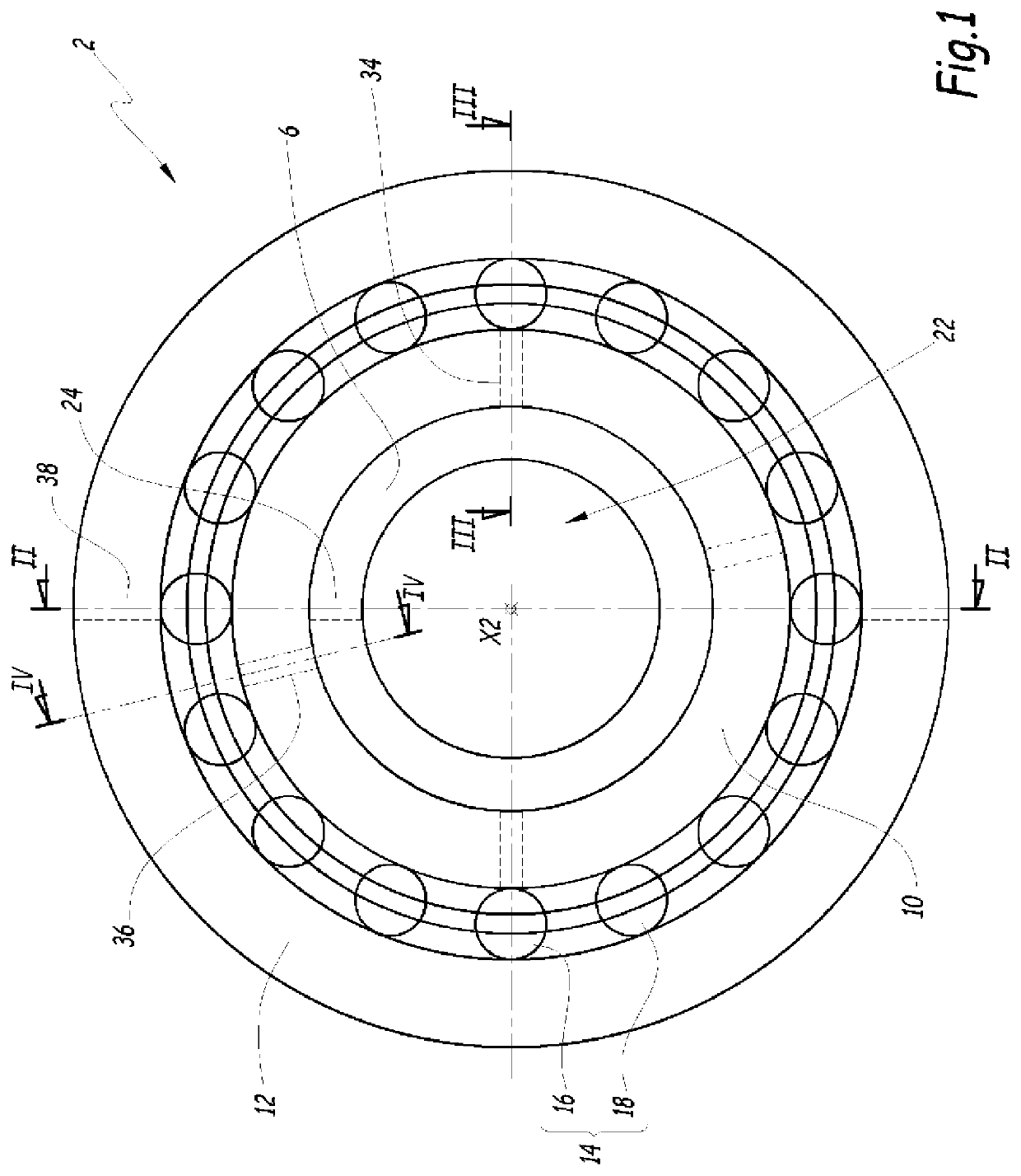
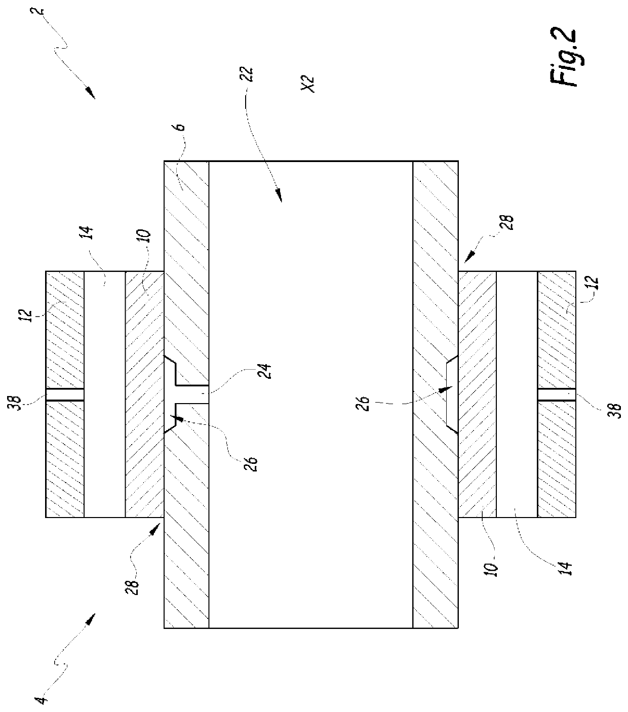
[0042]FIGS. 1 to 6 show a mechanical assembly 2 comprising a mechanical device 4 and a shaft 6. The shaft 6 extends along a longitudinal axis X2 of the assembly 2. For example, the shaft 6 is cylindrical in shape, with its centre on the axis X2.

[0043]According to embodiments, the device 4 comprises a bearing mounted on the shaft 6. For example, the device 4 is a rolling-element bearing such as a ball bearing. As a variant, the device 4 is a journal bearing or a spherical bearing.

[0044]As illustrated in FIGS. 1 to 4, the device 4 comprises a fixed ring 10 and a moving ring 12. The fixed ring 10 is mounted directly on the shaft 6 and the moving ring 12 is mounted around the fixed ring 10. Thus, in this instance the moving ring 12 is outside the fixed ring 10. The rings 10 and 12 are aligned coaxially around the axis X2. The fixed ring 10 is secured to the shaft 6 with no degree of freedom in rotation about the shaft 6. The moving ring 12 is free to rotate about the fixed ring 10, and ...

second embodiment

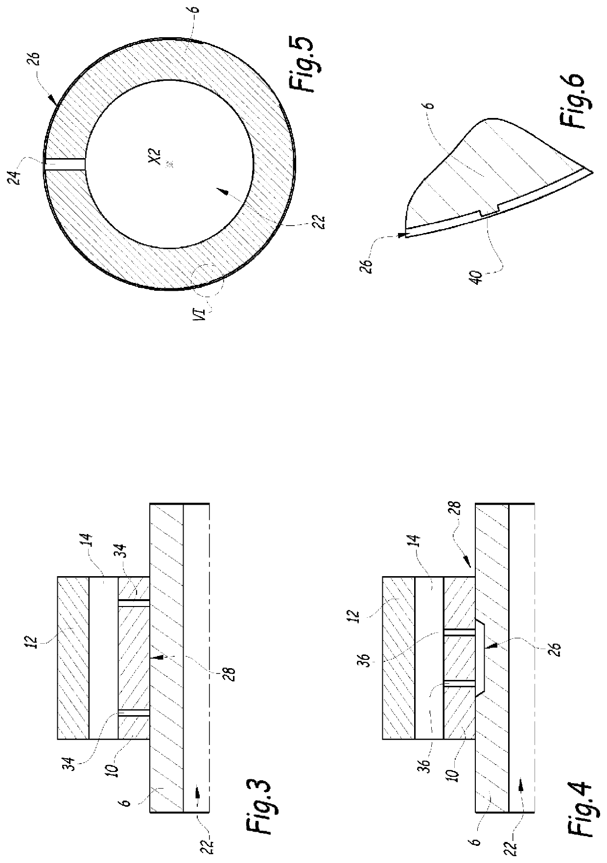
[0079]However, that is not illustrated, the channel 26 is formed on one or other of the shaft 6 and the bearing (in this case on the face 30 or on the face 32, respectively), and the constrictions 40 are formed on the other of the bearing and the shaft 6.

[0080]In this second embodiment, the constrictions 40 are preferably created in the form of elements, such as excrescences or attached parts, which project from the face on which they are formed and which extend into the channel 26 so as to constrict the section of the channel 26.

[0081]In one example, which is shown in FIG. 6, the channel is formed on the outer face 30 of the shaft and each of the one or more constrictions 40 associated with this channel include an element, in particular an excrescence or an attached element, formed on the inner face 32 and extending into the channel.

[0082]In another example, which shown in FIG. 4A, the channel is formed on the inner face 32 of the bearing and each of the one or more constrictions ...

third embodiment

[0084] which is not illustrated, the channel and the one or more constrictions 40 are formed on the inner face 32 and therefore on the device 4 (in particular on the fixed ring 10). In this case, the system 20 is completely integrated into the device 4. However, when the feed of lubricant fluid is provided by the shaft 6 as described above, then the dimensions of the system 20 are adapted accordingly, in particular in order that the channels 26 formed on the bearing of the device 4 be aligned with the feed orifices 24. In this embodiment, the orifices 24 opening at the surface 30 of the shaft 6 are considered to open within the channels 26, despite the channels 26 being formed on the face 32, since the face 32 is preferably arranged at a small distance from the face 30 and the orifices 24 are located facing the open part of the channels 26.

[0085]For example, the faces 30 and 32 are separated by a distance of less than or equal to 1 cm, or less than or equal to 5 mm, or less than or ...


PUM


Abstract

A mechanical assembly including a shaft, a mechanical device providing, a bearing mounted on the shaft and including at least one ring that is able to move in rotation about the shaft, a lubrication system having a channel to allow lubricant fluid to flow, formed at the interface between the shaft and the bearing, distribution ducts for lubricant fluid, formed in the bearing and fluidically connected to the channel. The channel provides at least one constriction to create a loss of head of the lubricant fluid flowing in the channel.

Description

CROSS-REFERENCE TO RELATED APPLICATIONS[0001]This application claims priority to French patent application no. 1856596 filed on Jul. 17, 2018, the contents of which are fully incorporated herein by reference.FIELD OF THE INVENTION[0002]The present invention relates to a mechanical assembly comprising a mechanical device. The invention also relates to a mechanical device.[0003]The invention relates in particular to the field of lubrication of mechanical devices such as bearings, for example ball bearings.BACKGROUND OF THE INVENTION[0004]Conventionally, a mechanical device such as a bearing comprises a fixed ring and a moving ring. The fixed ring is able to be mounted on a shaft while the moving ring is mounted coaxially around the fixed ring and can rotate about the latter. A raceway formed between the fixed and moving rings may comprise rolling elements such as balls or rollers.[0005]These mechanical devices may further comprise an integrated lubrication system for the purpose of su...

Claims


Application Information

Patent Timeline
Patent Type & Authority Patents(United States)
IPC IPC(8): F16C33/66F16C33/10F16C35/073
CPCF16C35/073F16C33/1065F16C35/12F16C33/66F16N1/00F16C33/6677F16C33/58F16C33/6659F16C33/76
Inventor SORLIER, BRUNOAURY, ALEXANDREMIOLANE, MATTHIEU
Owner SKF AEROSPACE FRANCE SAS
Why Eureka
Try Eureka