Dual polarization radar apparatus and radar signal processing method

a radar and signal processing technology, applied in the direction of climate sustainability, instruments, measurement devices, etc., can solve the problem of difficult for the weather radar with a single polarized wave to accurately estimate the intensity of rainfall, and achieve the effect of preventing the nyquist rate from decreasing

Active Publication Date: 2020-10-06
MITSUBISHI ELECTRIC CORP
View PDF20 Cites 1 Cited by
  • Summary
  • Abstract
  • Description
  • Claims
  • Application Information

AI Technical Summary

Benefits of technology

[0016]According to the present invention, because the linear-depolarization ratio calculator is configured to calculate the linear depolarization ratio which is either the ratio between the first reflected wave intensity and the third reflected wave intensity or the ratio between the second reflected wave intensity and the fourth reflected wave intensity where the first through fourth reflected wave intensities are calculated by the reflected-wave intensity calculator, there is provided an advantage of being able to calculate the linear depolarization ratio while preventing the Nyquist rate from decreasing, even when the three types of polarized-wave transmission / reception processing elements are repeatedly performed.

Problems solved by technology

However, because this relational expression changes greatly dependently on a particle size distribution of raindrops, it is difficult for the weather radar with a single polarized wave to correctly estimate the intensity of rainfall.

Method used


Image

  • Dual polarization radar apparatus and radar signal processing method
  • Dual polarization radar apparatus and radar signal processing method
  • Dual polarization radar apparatus and radar signal processing method

Examples


embodiment 1

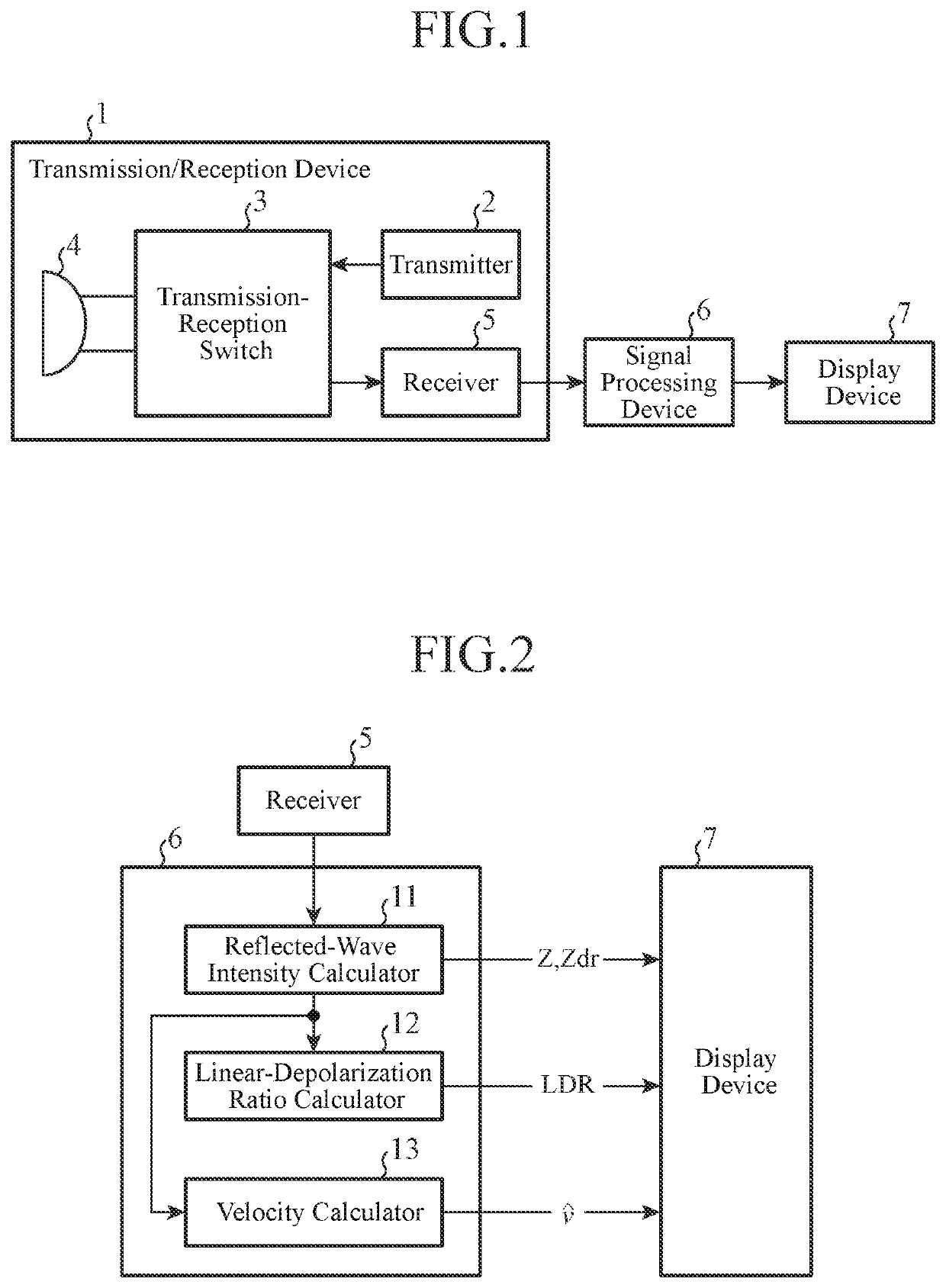
[0029]FIG. 1 is a block diagram showing a dual polarization radar apparatus according to Embodiment 1 of the present invention.

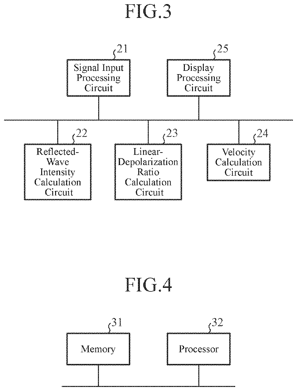
[0030]Further, FIG. 2 is a block diagram showing a signal processing device 6 of the dual polarization radar apparatus according to Embodiment 1 of the present invention, and FIG. 3 is a hardware block diagram of the signal processing device 6 shown in FIG. 2.

[0031]In the configurations shown in FIGS. 1 to 3, the transmission / reception device 1 is comprised of a transmitter 2, a transmission-reception switch 3, an antenna 4 and a receiver 5, and repeatedly performs three types of polarized-wave transmission / reception processing elements which are shown below:

[0032](1) “Transmission of a horizontally polarized wave and reception of a horizontally polarized wave” which is first transmission / reception processing to transmit a horizontally polarized wave and receive a horizontally polarized wave;

[0033](2) “Transmission of a vertically polarized wave and receptio...

embodiment 2

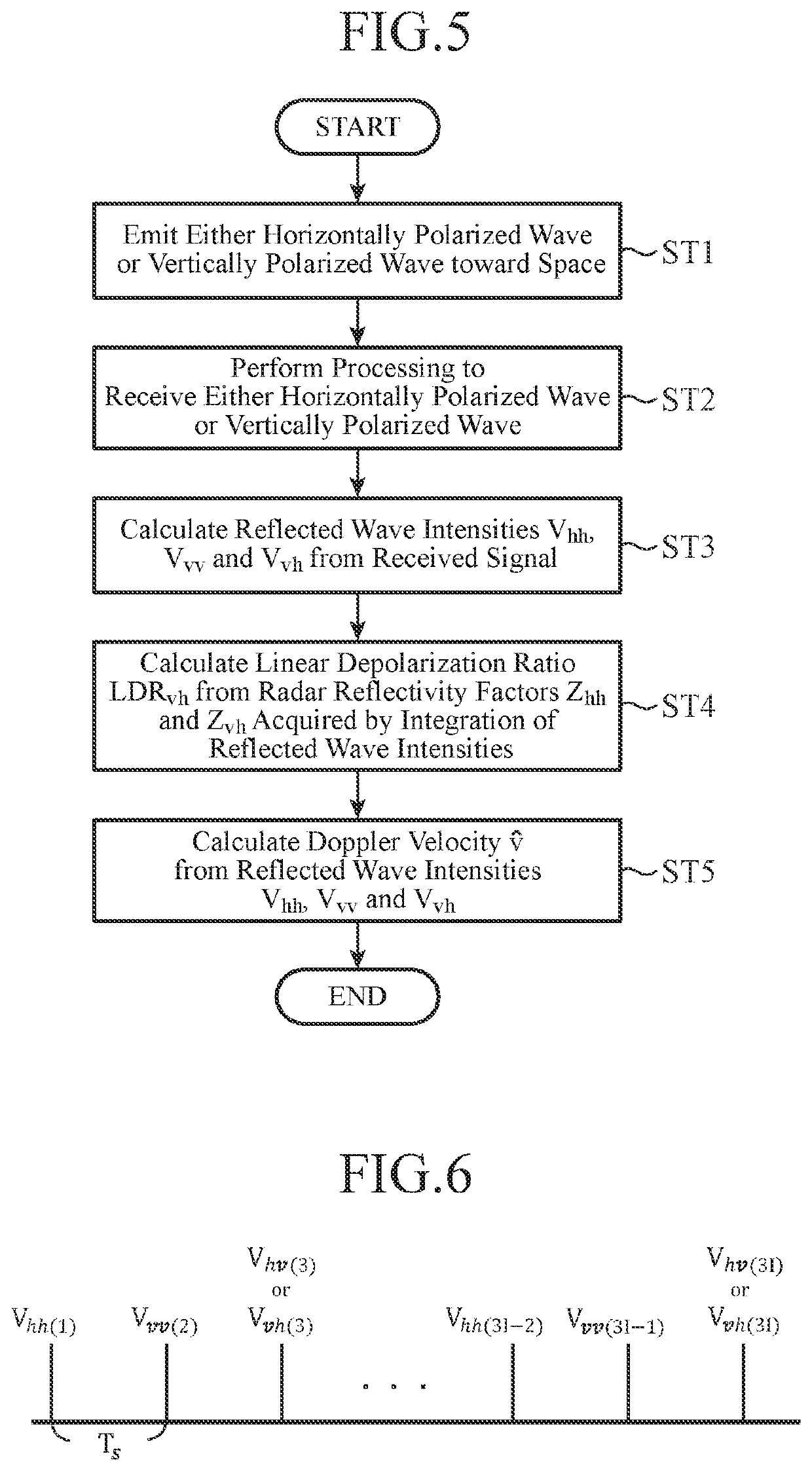
[0168]Although in above-mentioned Embodiment 1, the example in which the transmission / reception device 1 performs either “the transmission of a horizontally polarized wave and the reception of a vertically polarized wave” which is the third transmission / reception processing or “the transmission of a vertically polarized wave and the reception of a horizontally polarized wave” which is the fourth transmission / reception processing is shown, the transmission / reception device 1 can repeatedly perform the four types of polarized-wave transmission / reception processing elements by performing both “the transmission of a horizontally polarized wave and the reception of a vertically polarized wave” which is the third transmission / reception processing, and “the transmission of a vertically polarized wave and the reception of a horizontally polarized wave” which is the fourth transmission / reception processing.

[0169]FIG. 8 is an explanatory drawing showing an example in which the length of each ...

embodiment 3

[0241]FIG. 10 is a block diagram showing a signal processing device 6 of a dual polarization radar apparatus according to Embodiment 3 of the present invention. In FIG. 10, because the same reference numerals as those shown in FIG. 2 denote the same components or similar components, the explanations of the components will be omitted hereafter.

[0242]FIG. 11 is a hardware block diagram of the signal processing device 6 shown in FIG. 10. In FIG. 11, because the same reference numerals as those shown in FIG. 3 denote the same components or similar components, the explanations of the components will be omitted hereafter.

[0243]An availability determining unit 14 is implemented by an availability determination circuit 26 that includes a semiconductor processing circuit equipped with a CPU, a one chip microcomputer or the like, and performs processing to, when a radar reflectivity factor Zvh (or a radar reflectivity factor Zhv) calculated by a reflected-wave intensity calculator 11 is equal...


PUM


Abstract

A linear-depolarization ratio calculator (12) is configured so as to determine a radar reflectivity factor Zhh in transmission of a horizontally polarized wave and reception of a horizontally polarized wave, the radar reflectivity factor being a reflected wave intensity after integration of a reflected wave intensity Vhh(n) calculated by a reflected-wave intensity calculator (11), and a radar reflectivity factor Zvh in transmission of a horizontally polarized wave and reception of a vertically polarized wave, the radar reflectivity factor being a reflected wave intensity after integration of a reflected wave intensity Vvh(n+2) and calculate a linear depolarization ratio LDRvh which is the ratio between the radar reflectivity factor Zhh and the radar reflectivity factor Zvh. As a result, even when three types of polarized-wave transmission / reception processing elements are repeatedly performed, the linear depolarization ratio LDRvh can be calculated.

Description

TECHNICAL FIELD[0001]The present invention relates to a dual polarization radar apparatus and radar signal processing method for estimating the intensity of rainfall and / or a Doppler velocity by using a horizontally polarized wave and a vertically polarized wave.BACKGROUND ART[0002]In a widely-used weather radar with a single polarized wave, the intensity of rainfall is estimated from an echo intensity by using a relational expression established between the echo intensity and the intensity of rainfall. However, because this relational expression changes greatly dependently on a particle size distribution of raindrops, it is difficult for the weather radar with a single polarized wave to correctly estimate the intensity of rainfall.[0003]In general, a raindrop has a shape close to a spheroid which is like a sphere crushed in a perpendicular direction. A raindrop having a large particle diameter has a large degree of flatness, while a raindrop having a small particle diameter has a s...

Claims


Application Information

Patent Timeline
Patent Type & Authority Patents(United States)
IPC IPC(8): G01S13/95G01S7/42G01S7/02G01S13/58
CPCG01S13/95G01S7/025G01S7/42G01S13/581Y02A90/18Y02A90/10G01S7/024
Inventor KAWAI, MARIESAKAMAKI, HIROSHISUZUKI, NOBUHIROMATSUDA, TOMOYA
Owner MITSUBISHI ELECTRIC CORP
Why Eureka
Try Eureka