Method for offset compensation of a sensor signal of a hall sensor and sensor arrangement

a sensor signal and offset compensation technology, applied in the direction of magnetic field offset compensation, measurement devices, instruments, etc., can solve the problems of relatively high manufacturing cost of the corresponding hall sensor, the general effect of consuming a lot of time and avoiding system errors

Active Publication Date: 2020-10-20
FRAUNHOFER GESELLSCHAFT ZUR FOERDERUNG DER ANGEWANDTEN FORSCHUNG EV
View PDF23 Cites 1 Cited by
  • Summary
  • Abstract
  • Description
  • Claims
  • Application Information

AI Technical Summary

Benefits of technology

[0016]Since, in reality, the external magnetic field frequently cannot be assumed to be exactly constant or the concept present still provides sufficient compensation results when the external magnetic field (i.e. the magnetic field intensity or flux density) remains within a predetermined region or there is no or only a negligibly small external magnetic field applied, a so-called “tolerance range” is introduced or provided for the “respective stability” of the external magnetic field. The tolerance range thus indicates that region within which the external magnetic field is allowed to change while determining the offset portion or residual offset portion. The tolerance range may, for example, indicate that the external magnetic field changes by less than 50%, 30%, 20%, 10%, 5%, 1% or 0.1% while determining the offset portion or residual offset portion, or that there is no or only a negligibly small external magnetic field. The smaller the tolerance range which can be assumed and kept, the more precisely can the offset compensation be performed.
[0036]One characteristic of the present concept is that the offset portion of a sensor output signal of a Hall sensor can be determined at least approximately during operation, with no complicated serial test or calibration at partly different temperatures being used before for offset compensation.

Problems solved by technology

This calibrating process generally proves to be very (time-) consuming since the temperature-dependent offset portion of the Hall sensors to be compensated has to be measured at different temperatures in a serial test and then be stored in the Hall sensor for the offset correction.
This offset compensation is highly time-consuming and thus causes relatively high manufacturing costs for the corresponding Hall sensors.
Using the present concept for offset compensation, it is not only possible to perform the offset portion during operation and with no previous calibration and no previous serial test of the Hall sensor, but it is also possible to recognize errors in the entire system or the entire circuit arrangement, since the offset portion of the Hall sensors during operation is still known and consequently conclusions as to system errors can be drawn.
Up to now, this has not been possible since, up to know, differentiation between a sensor offset drift and an amplifier offset drift within the circuit arrangement has not been possible and, consequently, no conclusion could be drawn in this respect.

Method used


Image

  • Method for offset compensation of a sensor signal of a hall sensor and sensor arrangement
  • Method for offset compensation of a sensor signal of a hall sensor and sensor arrangement
  • Method for offset compensation of a sensor signal of a hall sensor and sensor arrangement

Examples


Embodiment Construction

[0050]Before embodiments of the present concept will be discussed below in greater detail referring to the Figures, it is pointed out that identical elements, objects, functional blocks and / or method steps or those of equal function or equal effect, in the different figures, are provided with same reference numerals so that the description, illustrated in the different embodiments, of these elements, objects, functional blocks and / or method steps is mutually exchangeable or mutually applicable.

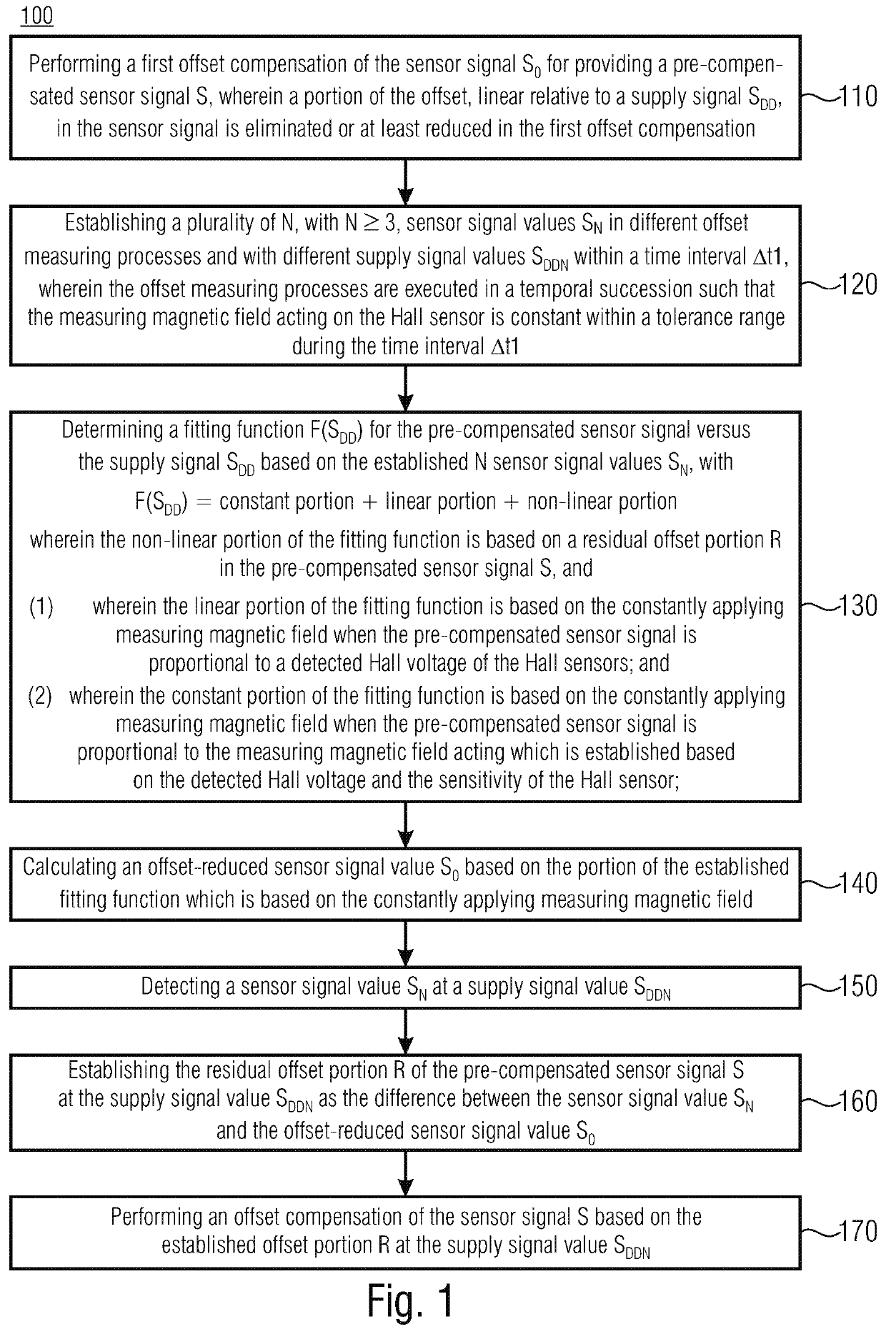
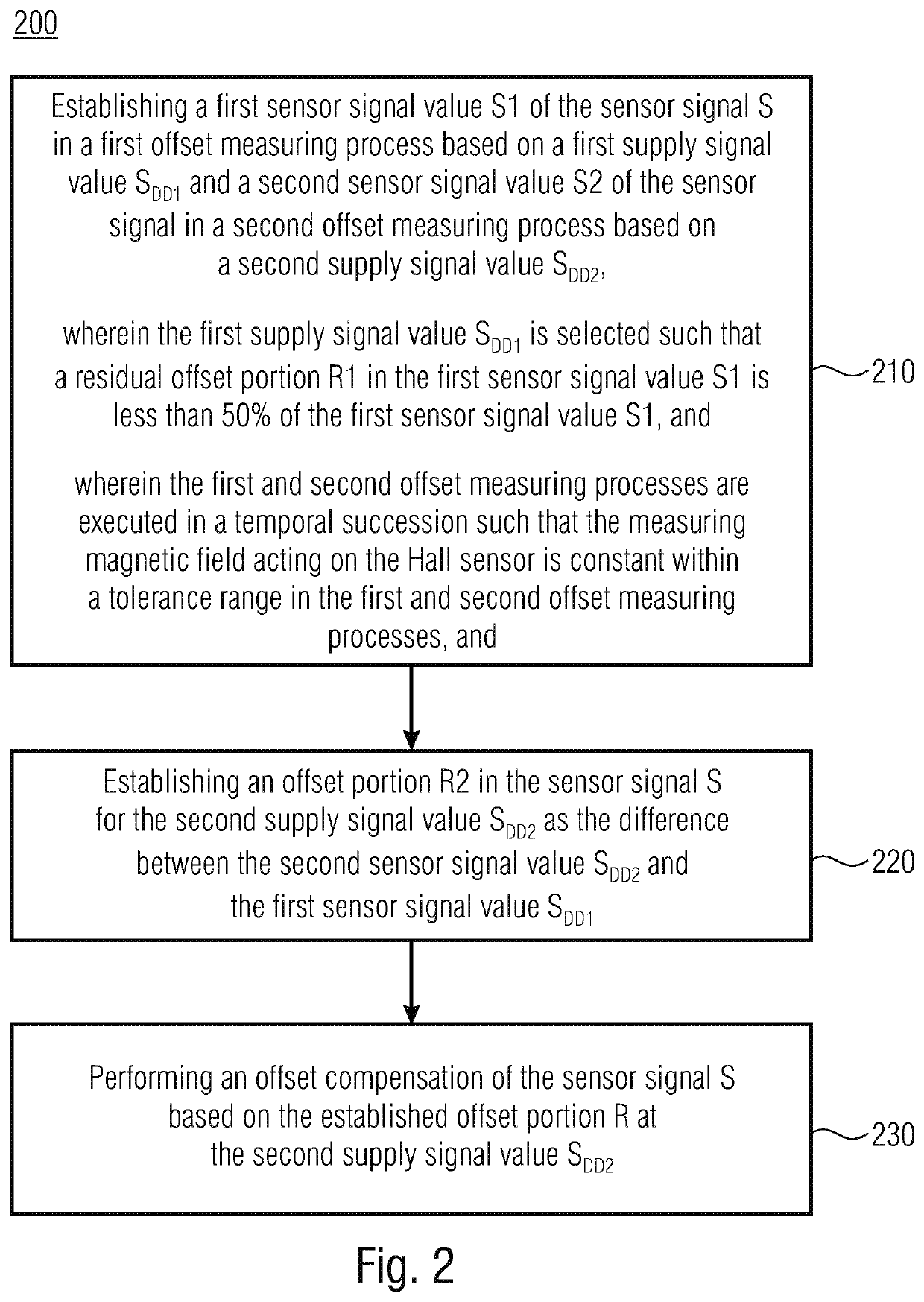
[0051]FIGS. 1 and 2 shows flow charts of the inventive concept for offset compensation of a sensor output signal of a Hall sensor by means of modulation or variation of the supply signal, like of the supply voltage or supply current. A Hall sensor may exemplarily comprise a Hall effect sensor element or a plurality of (exemplarily interconnected) Hall effect sensor elements. The sensor signal may be a sensor output signal of an individual Hall effect sensor element or a combination of sensor o...


PUM


Abstract

A central idea of techniques herein is that by means of modulation or variation of the supply signal of a Hall sensor, the useful signal portion in the resulting sensor output signal can be separated from the offset portion during operation of the Hall sensor, with no previous calibration or previous serial tests. That course of the sensor output signal resulting from the modulation or variation of the supply signal can then be evaluated or decomposed relative to the components which can be attributed to the offset portion and the useful signal portion. Thus, the offset portion in the sensor output signal can be determined with no (or a negligibly small) external magnetic field applied or with an external magnetic field applied, in case the external magnetic field is constant within a tolerance range while determining the offset portion.

Description

CROSS-REFERENCE TO RELATED APPLICATION[0001]This application claims priority from German Application No. 10 2016 225 305.0, which was filed on Dec. 16, 2016, and is incorporated herein by reference in its entirety.BACKGROUND OF THE INVENTION[0002]Embodiments relate to a device and a method for offset compensation of a sensor signal of a Hall sensor, and to a sensor arrangement comprising a Hall sensor and processing means for performing the method. In particular, embodiments relate to a concept for offset compensation of a sensor output signal of a Hall sensor by means of modulation or variation of the supply signal, wherein, by modulating the supply voltage of the Hall sensor, the offset portion in the sensor output signal may also be determined using an external magnetic field applied, for example, in case the external magnetic field is constant within a tolerance range while determining the offset portion.[0003]When an electric current flows through a Hall sensor and when a magne...

Claims


Application Information

Patent Timeline
Patent Type & Authority Patents(United States)
IPC IPC(8): G01R33/07G01R33/00
CPCG01R33/075G01R33/07G01R33/0064G01R33/0029G01R33/0017
Inventor STAHL-OFFERGELD, MARKUSSAND, MARKUSHOHE, HANS-PETER
Owner FRAUNHOFER GESELLSCHAFT ZUR FOERDERUNG DER ANGEWANDTEN FORSCHUNG EV
Why Eureka
Try Eureka