Autonomous retarder system for a vehicle, and vehicle including same

a technology of automatic retarder and vehicle, which is applied in the direction of braking system, asynchronous induction clutch/brake, electric device, etc., can solve the problems of wear and the need for constant and periodic maintenance, reduce passenger comfort, and the requirements for batteries are quite demanding

Active Publication Date: 2020-11-10
RALENTIZADORES Y TRANSFORMACIONES
View PDF9 Cites 2 Cited by
  • Summary
  • Abstract
  • Description
  • Claims
  • Application Information

AI Technical Summary

Benefits of technology

[0006]The object of the invention is a retarder system for a vehicle that resolves or at least mitigates the problems and limitations observed in the prior art.

Problems solved by technology

This type of brake presents problems of wear and the need for constant and periodic maintenance.
Also, the noise level of these systems decreases passenger comfort.
The requirements for these batteries are quite demanding because a large amount of current (approximately 160 A) is required.
While these requirements can be fulfilled using the existing technology, these batteries are generally large and costly.
On the other hand, if a battery is shared with other devices on the vehicle, the energy stored may be insufficient.
Regardless of which option is applied, the power supply generally cannot be integrated into the retarder, and the retarder is not compact.

Method used


Image

  • Autonomous retarder system for a vehicle, and vehicle including same
  • Autonomous retarder system for a vehicle, and vehicle including same
  • Autonomous retarder system for a vehicle, and vehicle including same

Examples


Embodiment Construction

[0030]The figures describe several examples of embodiments but do not limit the invention.

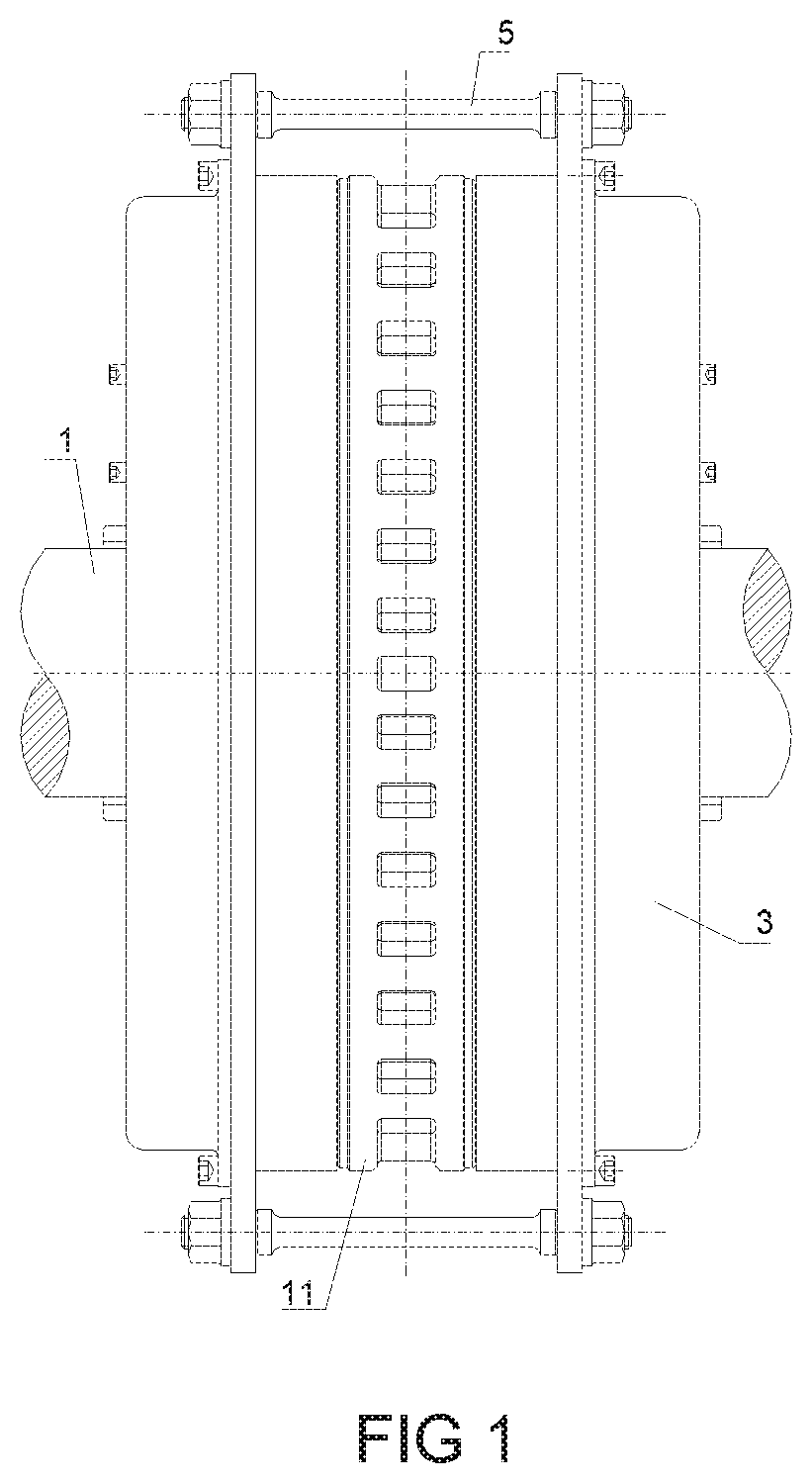
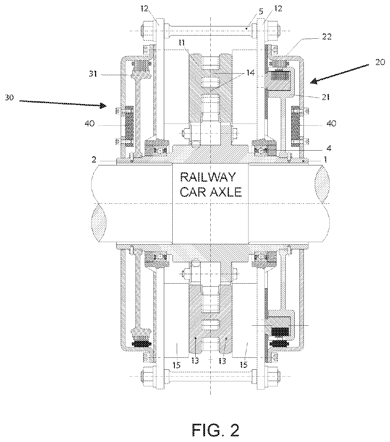
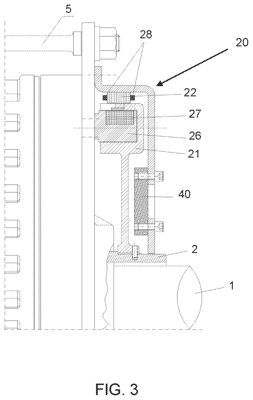
[0031]Note that the selected configuration is not the customary configuration with two external rotors and an intermediate stator. The axial arrangement of one rotor and two stators is proposed as an alternative in the embodiments described here. The retarder rotor is positioned centrally, with the stators positioned on either side of it. This configuration mitigates problems of rotor locking caused mainly by exposure to weather. In cold climates, blocks of ice may form on the rotors, which could damage nearby elements if they are thrown off during rotation.

[0032]There are other advantages to selecting a central rotor. One is that it provides fixed air gaps. Another is that it can function regardless of the direction of rotation. The direction of rotation is especially important for cooling. With external rotors, when they rotate in one direction, air is forced into the retarder to cool it. Coo...


PUM


Abstract

The invention relates to an autonomous retarder system for a vehicle including a retarder (10) having a central rotor (11) and two stators (12), one on each side of the rotor (11). The rotor (11) is rigidly coupled to an axle (1). A generator (20, 30, 50) is also included, coupled to the retarder (10), for supplying same with electrical energy. In addition, the generator (20, 30, 50) comprises a stator (22) and a rotor (21, 31, 51) coupled to the retarder.

Description

CROSS REFERENCE TO RELATED APPLICATION[0001]This Application is a 371 of PCT / ES2014 / 070655 filed on Aug. 14, 2014, which is incorporated herein by reference.TECHNICAL FIELD OF THE INVENTION[0002]The invention belongs to the field of braking systems for vehicles, and specifically for trains. More specifically, it corresponds to electromagnetic braking systems that use the principle of Foucault currents.BACKGROUND OF THE INVENTION OR STATE OF THE ART[0003]The majority of braking systems are based on mechanical friction to reduce speed. This type of brake presents problems of wear and the need for constant and periodic maintenance. Also, the noise level of these systems decreases passenger comfort.[0004]For this and other reasons, efforts have been made to apply other principles for braking. Specifically, auxiliary brakes that serve as a support to friction-based brakes have been designed. One notable option consists of electrical brakes that are activated based on the induction of Fou...

Claims


Application Information

Patent Timeline
Patent Type & Authority Patents(United States)
IPC IPC(8): B60L7/28H02K7/18H02K49/04B60L1/00B60L7/26B60T8/17B60T13/74B61H11/04F16D63/00F16D65/78F16D121/20
CPCB60L7/26B60T8/1705B61H11/04B60L1/003H02K7/1846F16D65/78H02K7/1807B60L7/28B60T13/748H02K49/046F16D63/002F16D2121/20Y02T10/64B60L2220/42B60L2220/14F16D2065/788B60L2200/26B60L2220/12B60L2240/421
Inventor CARBALLO RODRIGUEZ, PABLO
Owner RALENTIZADORES Y TRANSFORMACIONES
Why Eureka
Try Eureka