Rotor type sprinkler with reversing mechanism including sliding clutch and driven bevel gears

a rotor type, clutch technology, applied in the direction of spraying apparatus, movable spraying apparatus, etc., can solve the problems of inconvenient use of reversing mechanism, complex arrangement of rotor type sprinklers, unsuitability for use in pop-up sprinklers with horizontal turbines and gear trains, etc., to achieve a simple clutch mechanism

Inactive Publication Date: 2006-05-09
HUNTER INDUSTRIES
View PDF13 Cites 52 Cited by
  • Summary
  • Abstract
  • Description
  • Claims
  • Application Information

AI Technical Summary

Benefits of technology

[0010]It is another object of the present invention to provide a more compact reversing mechanism for a rotor type sprinkler.
[0011]It is still another object of the present invention to provide a reversing mechanism for a rotor type sprinkler that has a simpler clutch mechanism.

Problems solved by technology

Many regions of the world have inadequate rainfall to support lawns, gardens and other landscaping during dry periods.
Reversing mechanisms in rotor type sprinklers have generally been complex arrangements.
While the foregoing designs patented by Hunter have been commercially successful, they have space requirements that make them unsuitable for use in a pop-up sprinkler with a horizontal turbine and gear train reduction.
Furthermore, they rely on the engagement of gear teeth with traditional tapers which do not perform a clutching function very well.
If a maintenance worker, or a vandal, manually rotates the turret containing the nozzle relative to the lower outer housing of the sprinkler, the gear teeth do not slip over each other easily without resultant damage.

Method used


Image

  • Rotor type sprinkler with reversing mechanism including sliding clutch and driven bevel gears
  • Rotor type sprinkler with reversing mechanism including sliding clutch and driven bevel gears
  • Rotor type sprinkler with reversing mechanism including sliding clutch and driven bevel gears

Examples


Embodiment Construction

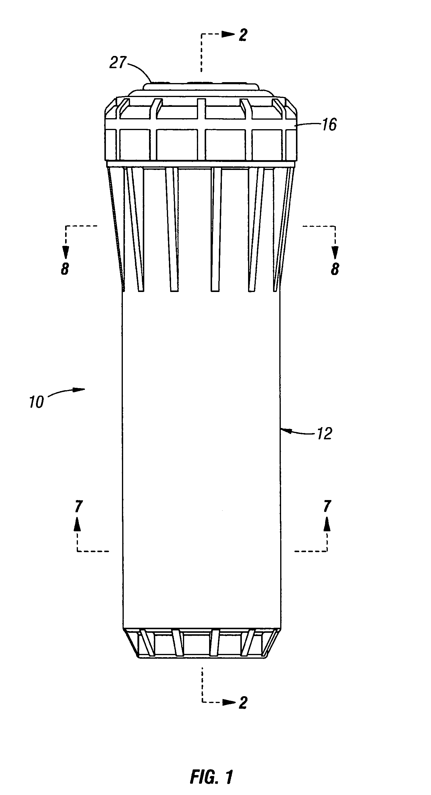
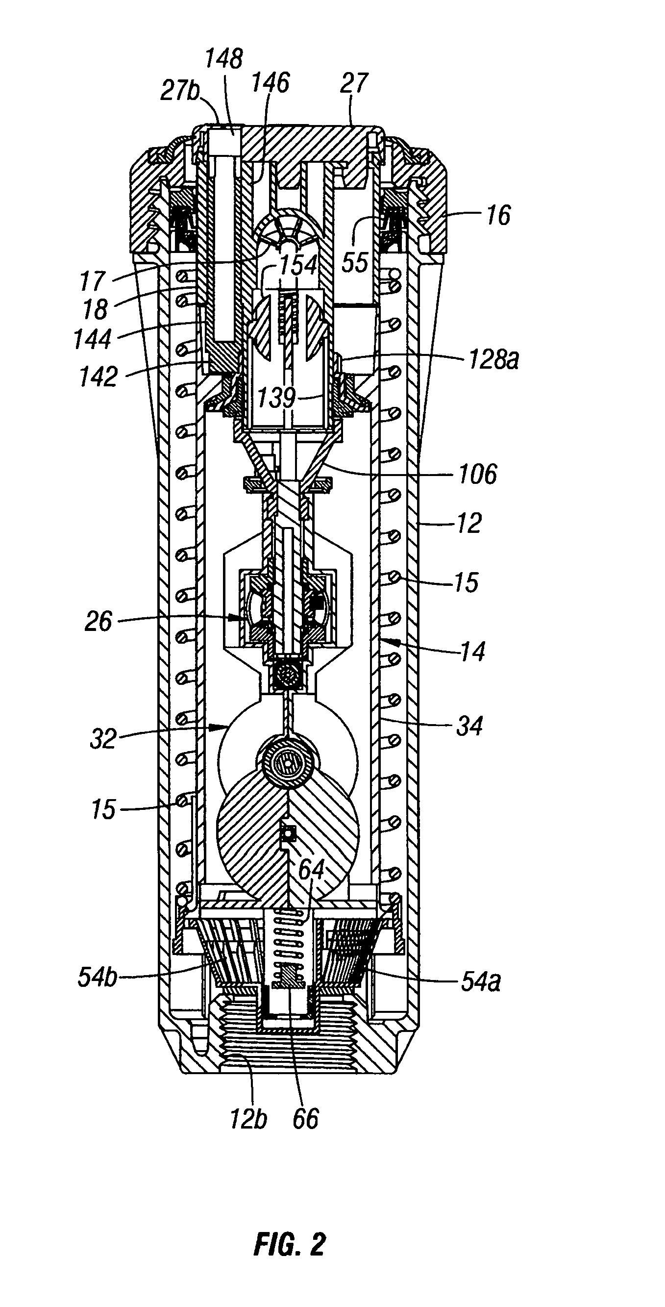
[0108]In accordance with the present invention, a pop-up rotor type sprinkler 10 (FIG. 1) includes an outer cylindrical housing 12 having a lower end connectable to a source of pressurized water (not illustrated) and an inner cylindrical riser 14 (FIGS. 11–15) that is vertically reciprocable along a vertical axis within the outer housing 12 between extended and retracted positions when the source of pressurized water is turned ON and OFF. The retracted or lowered position of the riser 14 is illustrated in FIGS. 2 and 4. The extended or raised position of the riser 14 is illustrated in FIGS. 80 and 81. The sprinkler 10 is normally buried in the ground with its upper end level with the surface of the soil. The riser 14 pops up to spray water on the surrounding landscaping in response to commands from an electronic irrigation controller that turn a solenoid actuated water supply valve ON in accordance with a water program previously entered by a homeowner or by maintenance personnel. W...


PUM


Abstract

A Pelton type turbine is mounted in a riser of a pop-up sprinkler for rotation about a horizontal axis and drives a central bevel pinion gear through a gear train reduction. Upper and lower bevel gears supported on a vertical drive shaft are simultaneously driven in opposite directions by the central bevel pinion gear. A clutch slides up and down along the drive shaft to engage radially extending teeth formed on its upper and lower sides with complementary teeth formed on the upper and lower bevel gears. One end of a yoke is coupled to the clutch and the other end is moved vertically by an over-center mechanism to shift the direction of rotation of a nozzle turret connected to the upper end of the drive shaft. The over-center mechanism is tripped back and forth by a shift disc engaged by a pair of tabs of a turret coupling assembly.

Description

FIELD OF THE INVENTION[0001]The present invention relates to irrigation equipment, and more particularly, to sprinklers of the type that use internal turbines to rotate a nozzle to distribute water over turf or other landscaping.BACKGROUND OF THE INVENTION[0002]Many regions of the world have inadequate rainfall to support lawns, gardens and other landscaping during dry periods. Sprinklers are commonly used to distribute water over such landscaping in commercial and residential environments. The water is supplied under pressure from municipal sources, wells and storage reservoirs.[0003]So called “hose end” sprinklers were at one time in widespread use. As the name implies, they are devices connected to the end of a garden hose for ejecting water in a spray pattern over a lawn or garden. Fixed spray head sprinklers which are connected to an underground network of pipes have come into widespread use for watering smaller areas.[0004]Impact drive sprinklers have been used to water landsc...

Claims


Application Information

Patent Timeline
Patent Type & Authority Patents(United States)
IPC IPC(8): B05B3/00B05B3/04B05B15/10
CPCB05B3/0431B05B3/0459B05B15/10B05B15/74
Inventor CLARK, MICHAEL L.
Owner HUNTER INDUSTRIES
Why Eureka
Try Eureka