
Adjustable sprinkler

a technology of adjustable sprinklers and sprinklers, which is applied in the field of adjustable sprinklers, can solve the problems of large amount of time and effort is thus required in the field, and the process is fairly time-consuming and labor-intensive. achieve the effect of quick and efficient setting

Inactive Publication Date: 2005-09-08
BRUNINGA KENNETH
View PDF99 Cites 52 Cited by
  • Summary
  • Abstract
  • Description
  • Claims
  • Application Information

AI Technical Summary

Benefits of technology

[0027] It is an advantage of the present invention to provide an adjustable sprinkler including a spray pattern controller and a slip clutch which enables users to quickly and efficiently set the boundaries of a desired spray pattern and verify those boundaries.
[0028] Another advantage of the present invention is to provide an adjustable sprinkler that eliminates the need to remove the cap to set or adjust the boundaries of the spray pattern.
[0029] Additional features and advantages of the present invention are described in, and will be apparent from, the following

Problems solved by technology

This is a fairly time consuming process during the installment process and during servicing as further discussed below.
One problem with such adjustable sprinklers is that a user such as an installer or person servicing the system must spend a significant amount of time removing the caps from the head structures of the individual sprinklers and then setting the desired arc spray patterns for each of those sprinklers.
A significant amount of time and effort is thus required in the field to set up or adjust one or more adjustable sprinklers in a sprinkler system.
Another problem with such adjustable sprinklers is that when a user verifies the boundaries of the spray pattern, the slip clutch mechanism is rotated so that the teeth are moved along the grooves on the interior surface of the head structure.
As a result, a user has significant difficulty determining if the adjustment members are tripped.
Because some sprinkler systems include several different sprinklers, the amount of time spent adjusting the sprinklers can be significant.

Method used


Image

  • Adjustable sprinkler
  • Adjustable sprinkler
  • Adjustable sprinkler

Examples


Embodiment Construction

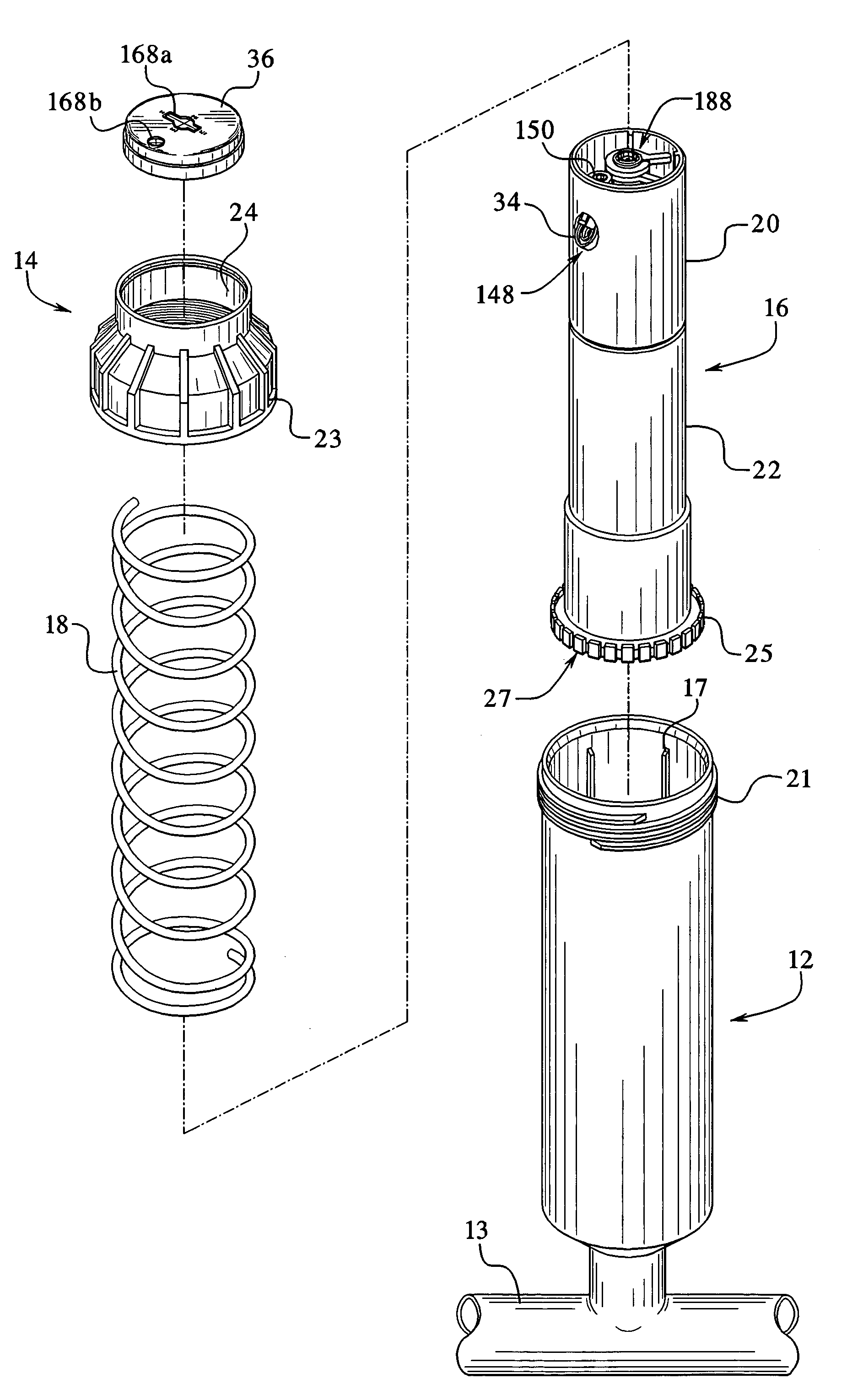
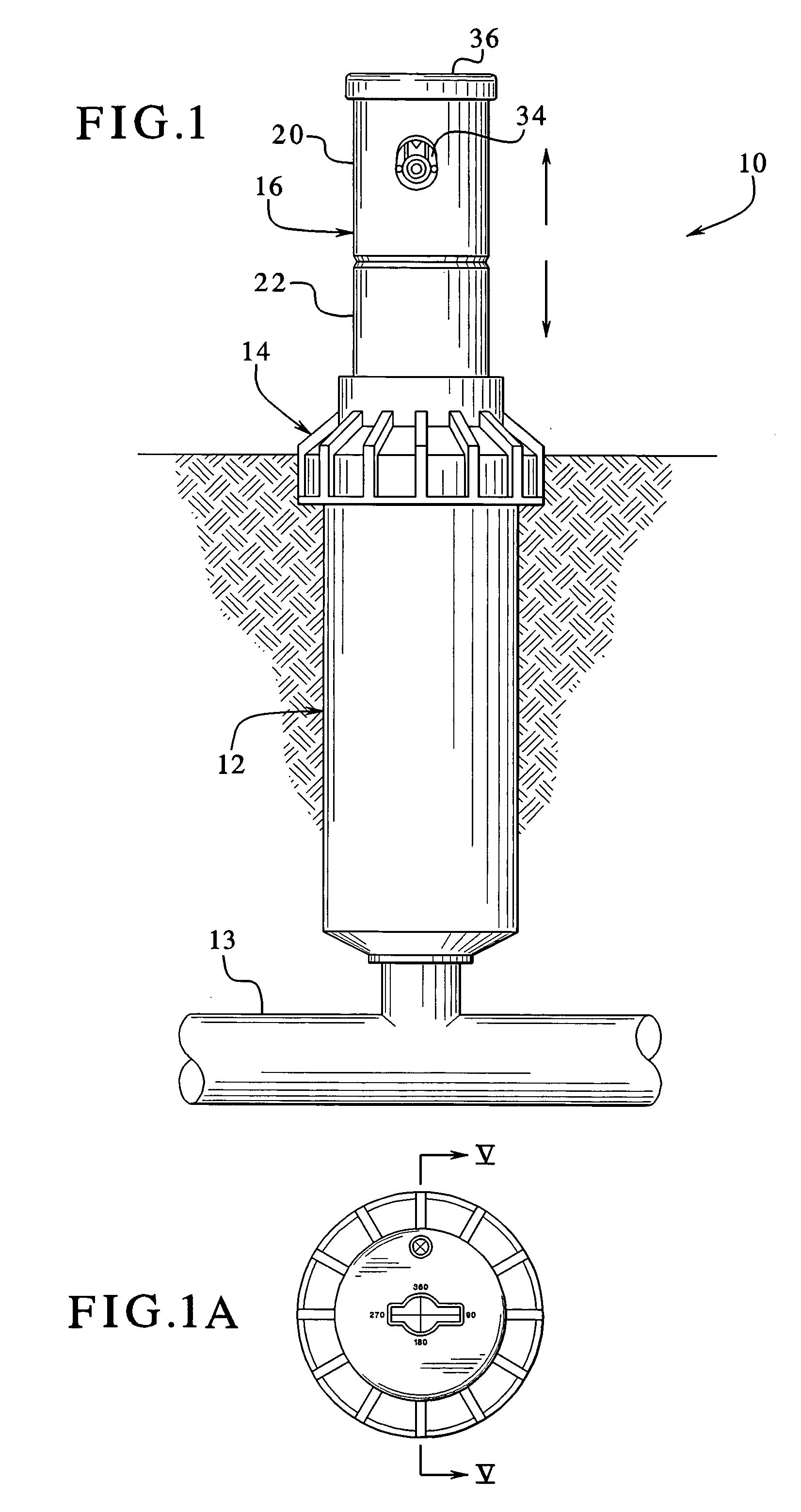
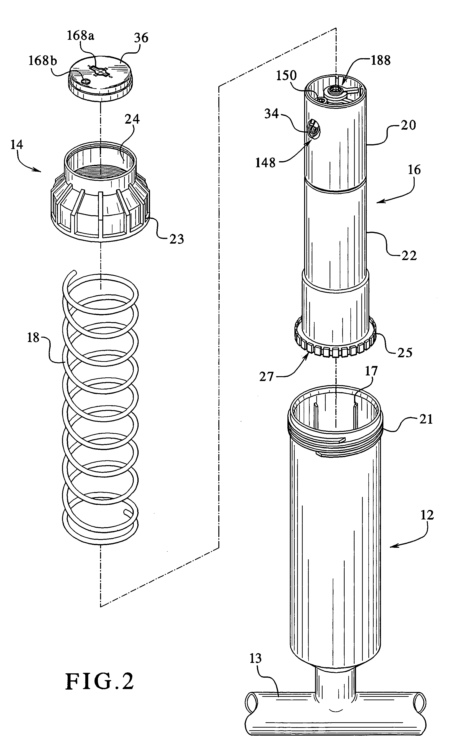
[0052] Referring now to the drawings and specifically to FIGS. 1 and 1A, one embodiment of the adjustable sprinkler, indicated by numeral 10, is generally illustrated. The in-ground or pop-up type adjustable sprinkler 10 includes an outer housing 12 suitably connectable to a pressurized water pipe 13, a positioner 14 which is threadingly engaged to the top of the outer housing 12 and an inner housing or turret 16 which is slideably mounted in the outer housing 12 and which extends through the positioner 14. The outer housing 12 defines a water inlet 15 (see FIG. 5) which is adapted to receive pressurized water from the pipe 13. As the pressurized water enters the outer housing through the water inlet 15, the pressure of the water pushes upwardly against the inner housing to cause the inner housing to move upwardly through the positioner 14 to a fully extended or operative position. In this position, the pressurized water is directed upwardly through the inner housing and to a suitab...


PUM


Abstract

An adjustable sprinkler including an inner housing slideably engaged with an outer housing. The inner housing includes a head rotatably mounted to a body. The outer housing includes an inlet which receives pressurized water and transfers the pressurized water to a nozzle attached to the head. The inner housing includes a reverser for selectively driving an impeller in two different directions. The impeller is connected to a reducer which reduces the rotational rate transferred from the impeller to the head and also enables the head to be manually rotated without causing damage to the internal components of the adjustable sprinkler. The head includes a click set and a cap. The cap defines at least one opening to enable a user to insert a tool through the cap to adjust and set the boundaries of the spray pattern using the click set.

Description

BACKGROUND OF THE INVENTION [0001] Several different types of known irrigation devices such as sprinklers are used to irrigate lawns, garden beds, landscaping, fields, crops and other similar areas. One type of known irrigation device is an oscillating sprinkler which is commonly used by homeowners to water their lawns, bushes, trees and gardens. Such oscillating sprinklers are manually placed in an area to be watered and manually connected to a hose or other pressurized water source. The pressurized water activates the sprinkler and causes the sprinkler to oscillate or move back and forth about a substantially horizontally disposed axis. Other types of sprinklers that emit water in different spray patterns such as circular spray patterns are also known. Generally, however, these types of sprinklers must be manually placed in the desired watering location or locations by a user to water the desired irrigation areas. Therefore, oscillating sprinklers and other similar above-ground sp...

Claims


Application Information

Patent Timeline
IPC IPC(8): B05B12/08
CPCB05B15/10B05B3/0436B05B15/74
Inventor BRUNINGA, KENNETH
Owner BRUNINGA KENNETH
Learn More