Methods and systems for imaging orthodontic aligners

a technology of orthodontic aligners and imaging methods, applied in the field of imaging orthodontic aligners, can solve the problems of difficult to predict or measure the full interaction between the aligner and the teeth, and achieve the effect of improving the accuracy of orthodontic aligner positioning and alignmen

Active Publication Date: 2020-11-24
ALIGN TECH
View PDF647 Cites 0 Cited by
  • Summary
  • Abstract
  • Description
  • Claims
  • Application Information

AI Technical Summary

Benefits of technology

[0018]The apparatuses described herein may be configured to determine the boundary between the appliance (e.g., aligner) and the patient's dentition by any appropriate method, including, for example, by segmenting the 3D model. When OCT is used to generate images through the teeth and aligner, for example, the resulting images may be combined and used to form a 3D volumetric model of the teeth and aligner. This model may be segmented to identify separate regions. Segmentation may include direct segmentation of the penetrative images. This may allow for the identification of dentin within the teeth, including the location and morphology of the dentin, the identification of the aligner, as well as the identification and location of cracks, lesions, and / or caries in the teeth, including in the dentin. The use of segmentation may allow for reconstruction of a volumetric model based on the penetrative images and the knowledge of the camera position corresponding to the penetrative images. A volumetric model of teeth can be segmented and these segments (relating to different internal structures of the tooth and / or aligner) may be projected back to the images.

Problems solved by technology

The complex geometry and mechanics of aligners acting on teeth may make it difficult to predict or measure the full interaction between the aligner and the teeth when an aligner is worn.

Method used


Image

  • Methods and systems for imaging orthodontic aligners
  • Methods and systems for imaging orthodontic aligners
  • Methods and systems for imaging orthodontic aligners

Examples


examples

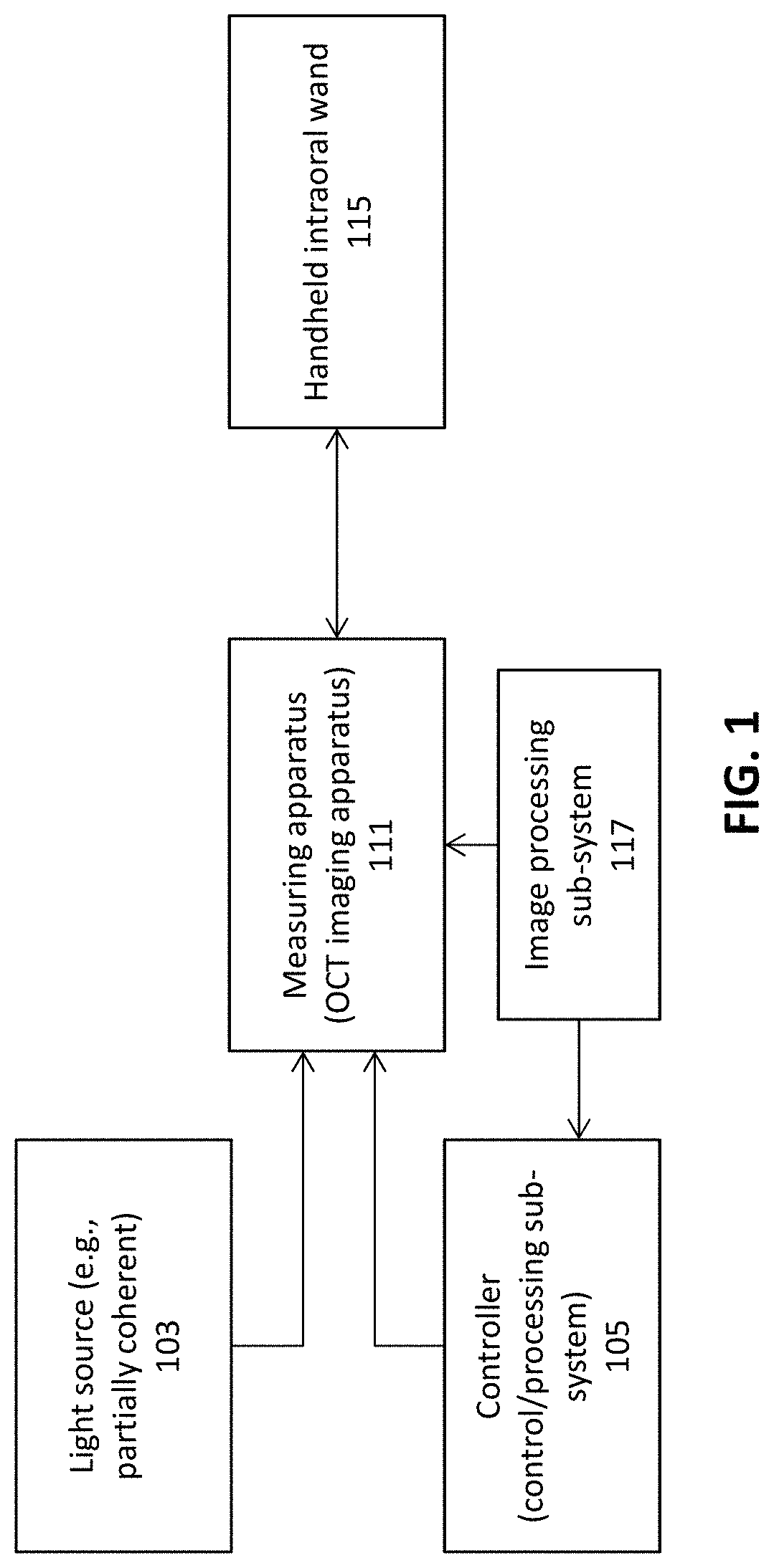
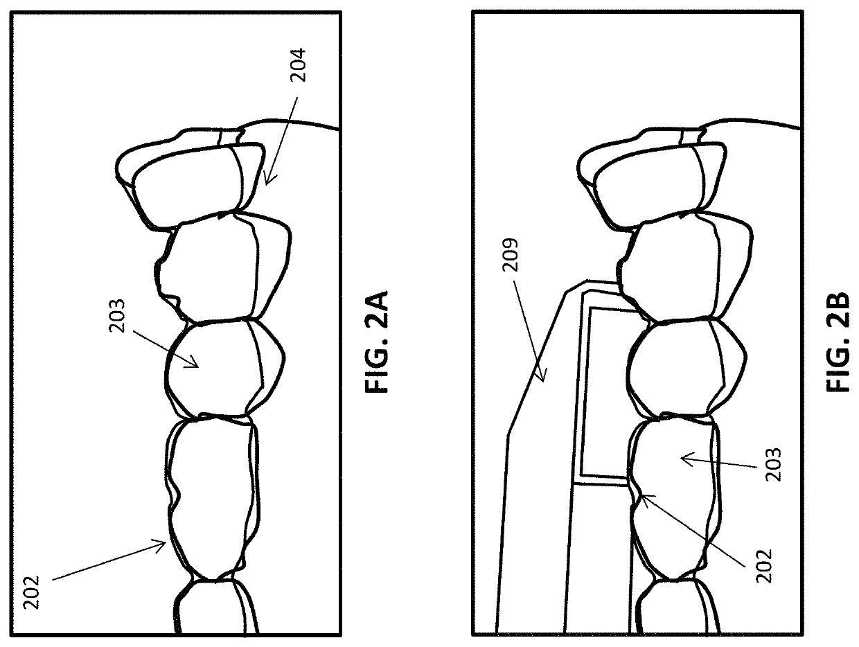
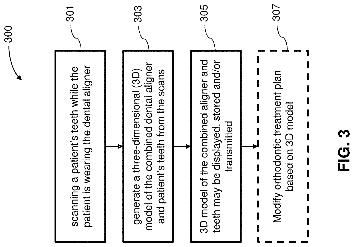
[0089]An OCT system may be used for scanning an aligner, or each aligner of a series of aligners, on a patient's teeth, in order to examine the aligner fit and the interaction with the patient's teeth. In some variations the OCT system may scan the patient's teeth and aligner directly, e.g., within the patient's oral cavity. In some variations, the OCT system may scan the patient's teeth and aligner indirectly, by scanning the aligner worn on a model (e.g., a cast) of the patient's teeth. In any of these variations, images of the aligner worn on the patient's teeth may be taken (recorded) for later analysis and / or analyzed immediately.

[0090]The scanning system may scan for a variety of fields of view (e.g., dimensions of the scanning field) and / or for various times. Scanning resolution may be, for example, between 1 and 100 microns (e.g., between 2 and 50 microns, between 5 and 30 microns, between 6-10 microns, between 6-30 microns, between 6-50 microns, etc.). As mentioned above, a...


PUM


Abstract

Methods and apparatuses for 3D imaging to measure the shape of orthodontic aligners, teeth, and other oral structures simultaneously, in-vivo or in-vitro. These methods and apparatuses may be used to determine contact locations of aligners with teeth and / or teeth with other teeth with very high precision, including determining the size of gaps where they are not in contact. These measurements may be used design, modify or replace an aligner and / or to verify aligner fit. 3D models of the whole aligner and teeth may be generated.

Description

CROSS REFERENCE TO RELATED APPLICATIONS[0001]This patent application is a continuation of U.S. patent application Ser. No. 16 / 048,054, filed Jul. 27, 2018, titled “OPTICAL COHERENCE TOMOGRAPHY FOR ORTHODONTIC ALIGNERS,” now U.S. Patent Application Publication No. 2019 / 0029522, which claims priority to U.S. Provisional Patent Application No. 62 / 537,937, filed Jul. 27, 2017, titled “OPTICAL COHERENCE TOMOGRAPHY FOR ORTHODONTIC ALIGNERS,” and is herein incorporated by reference in its entirety.[0002]This application may claim priority to U.S. patent application Ser. No. 15 / 662,234 (utility application), titled “INTRAORAL SCANNER WITH DENTAL DIAGNOSTICS CAPABILITIES,” filed Jul. 27, 2017, which is herein incorporated by reference in its entirety.INCORPORATION BY REFERENCE[0003]All publications and patent applications mentioned in this specification are herein incorporated by reference in their entirety to the same extent as if each individual publication or patent application was specif...

Claims


Application Information

Patent Timeline
Patent Type & Authority Patents(United States)
IPC IPC(8): A61B5/00A61C9/00A61C7/10A61C7/08G06T7/73A61C13/00G06T7/00G06T15/08A61C7/00
CPCG06T15/08A61C7/002A61C9/0053A61B5/7257A61B5/7425A61B5/0066G06T7/0014A61B5/4547G06T7/75A61B5/0088A61C7/10A61C7/08A61B5/4848A61C13/0004G06T2207/30036A61B2576/02G16H30/40
Inventor SATO, JUNBORONKAY, ALLENSHANJANI, YASERSHIRAZI AGHJARI, REZAKOPELMAN, AVIJANG, ANDREWCHENG, JIHUAKUO, ERICSHELBAKH, VLADIMIRPESENTI, BASTIEN
Owner ALIGN TECH
Why Eureka
Try Eureka