Transparent display system and operation method thereof

a display system and transparent technology, applied in the field of transparent display system and an operation method thereof, can solve the problems of affecting the difficulty of identifying display information

Active Publication Date: 2021-01-12
IND TECH RES INST +1
View PDF15 Cites 0 Cited by
  • Summary
  • Abstract
  • Description
  • Claims
  • Application Information

AI Technical Summary

Benefits of technology

[0007]An operation method of a transparent display system of the disclosure includes steps as follow: capturing a field luminance and a display information luminance of a display information, wherein the field luminance comprises a foreground reflective light luminance and a background transmissive light luminance; determining whether a luminance contrast of the display information may be recognized by a human eye, wherein the luminance contrast of the display information equals to the field luminance plus the display information luminance and then divided by the field luminance; if the luminance contrast of the display information is determined being recognized by the human eye, the display information is output; and if the luminance contrast of the display information is determined not being recognized by the human eye, the display information luminance is optimized, a display information size is optimized, a location of the display information is changed, or the field luminance is optimized.

Problems solved by technology

Therefore, under the condition that the display information luminance remains unchanged, the luminance contrast of the display information may be different because of the changes of the field, and further influences the difficulty of identifying the display information.

Method used


Image

  • Transparent display system and operation method thereof
  • Transparent display system and operation method thereof
  • Transparent display system and operation method thereof

Examples


Embodiment Construction

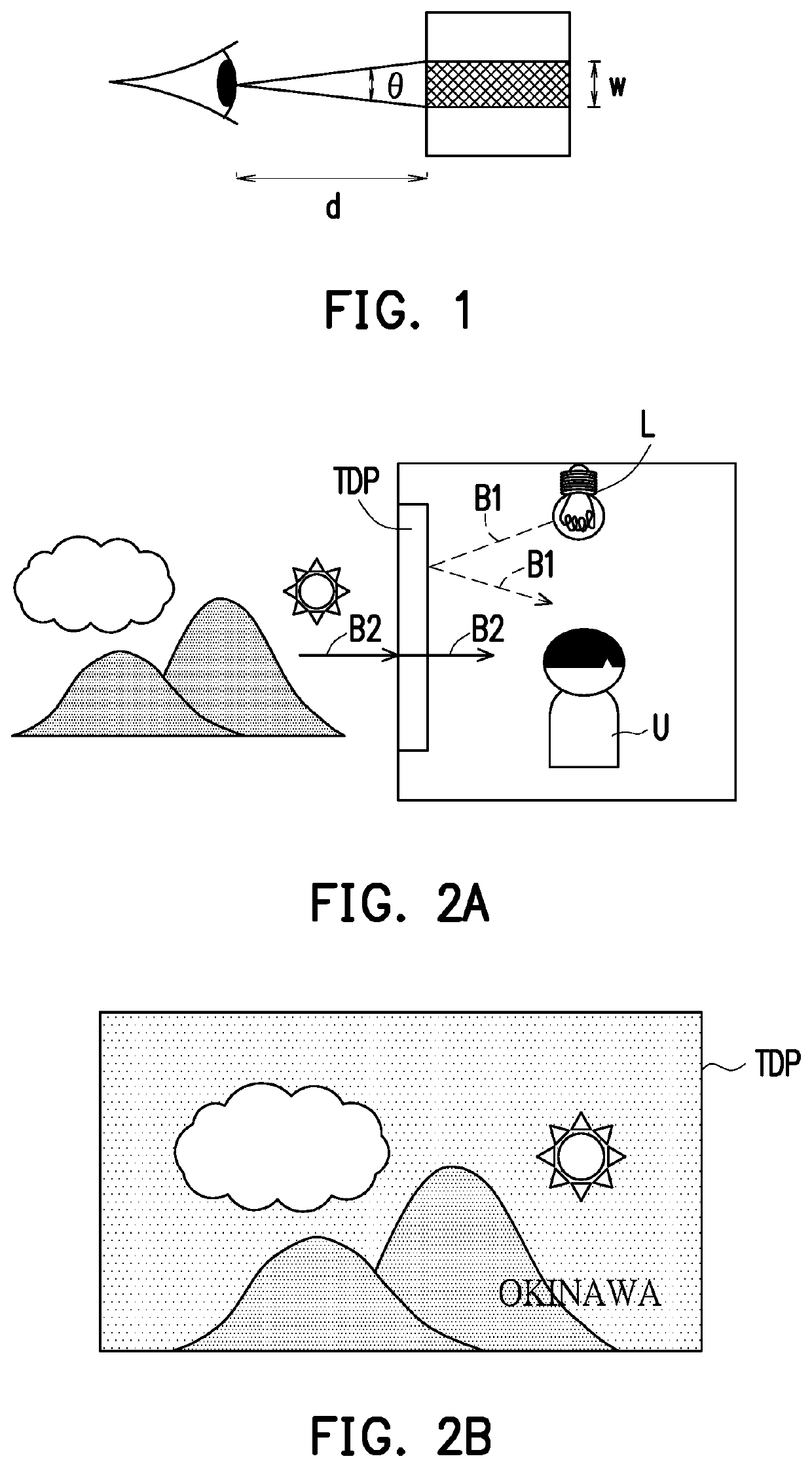
[0019]FIG. 1 is a schematic view explaining the minimum spatial resolution distinguished by a human eye. Generally, when a luminance contrast is 1, the minimum spatial resolution that can be clearly distinguished by a human eye is 1 / 60 degrees. In FIG. 1, θ is a viewing angle, w is a size of display information (e.g. a width of the strip in FIG. 1), and d is a distance between a user and the display information. According to FIG. 1, Formula 1 is inferred. The minimum spatial resolution that can be clearly distinguished by the human eye is θ= 1 / 60 degrees. That is, if θ is smaller than 1 / 60 degrees, the display information is difficult to be clearly distinguished.

[0020]θ=tan-1⁡(wd)Formula⁢⁢1

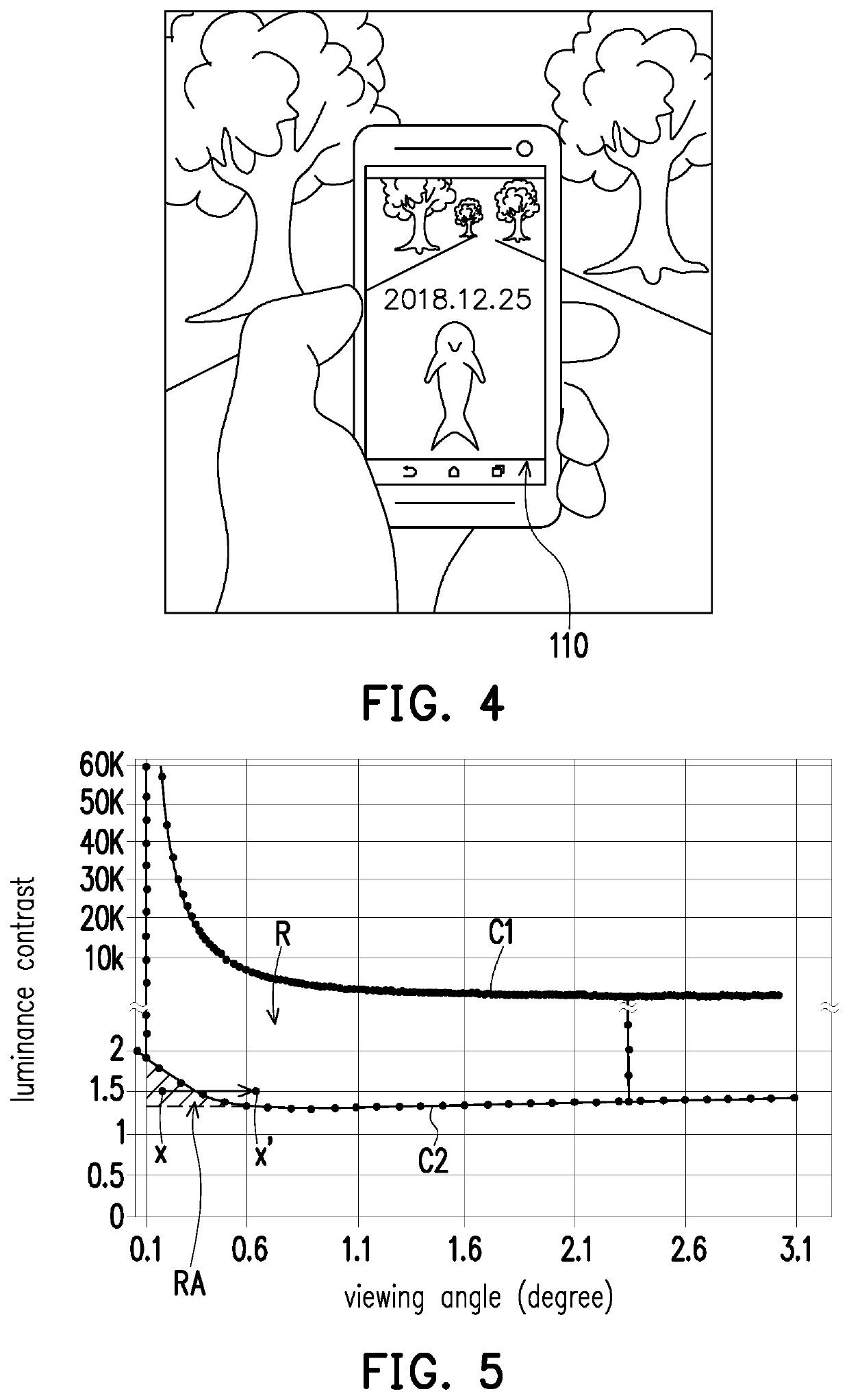
[0021]The study has found that the decrease in the luminance contrast of the display information leads to an increase of the minimum spatial resolution that can be clearly distinguished by the human eye. That is, the minimum spatial resolution that can be clearly distinguished by the human eye is ...


PUM


Abstract

A transparent display system including a display panel, a data acquisition module and a computation module is provided. The data acquisition is adapted to capture a field luminance of a field where the display panel is located and a display information luminance of display information of the display panel. The computation module determines whether a luminance contrast of the display information falls within a range from a lower boundary to an upper boundary, wherein the luminance contrast of the display information equals to the field luminance plus the display information luminance and then divided by the field luminance. If it is determined that the luminance contrast of the display information does not fall within the range from the lower boundary to the upper boundary, a luminance contrast optimization procedure is performed. An operation method of the transparent display system is also provided.

Description

CROSS-REFERENCE TO RELATED APPLICATION[0001]This application claims the priority benefit of Taiwan application serial no. 107125360, filed on Jul. 23, 2018. The entirety of the above-mentioned patent application is hereby incorporated by reference herein and made a part of this specification.BACKGROUNDTechnical Field[0002]The disclosure relates to a display system and an operation method thereof, and particularly related to a transparent display system and an operation method thereof.Description of Related Art[0003]A transparent display itself has a certain degree of transparency. Therefore, while displaying information, the transparent display displays a background behind the transparent display. Based on this transparent property, transparent displays are widely applied to a variety of fields, for example, building windows, car windows, or shop window, etc.[0004]When a background image and display information are both displayed on the transparent display, a luminance contrast of t...

Claims


Application Information

Patent Timeline
Patent Type & Authority Patents(United States)
IPC IPC(8): G09G5/10G09G5/373G09G5/38
CPCG09G5/10G09G5/373G09G5/38G09G2320/066G09G2320/0626G09G2320/0686G09G2354/00G09G2360/144G09G2360/145G09G2360/16G09G3/20G09G2340/045G09G2340/0464
Inventor KUO, SHIN-HONGLEE, CHENG-CHUNGCHEN, KUAN-TINGTSAI, YI-SHOULIN, YU-HSIN
Owner IND TECH RES INST
Why Eureka
Try Eureka