Organic electroluminescent device, display device, and illumination device
a technology of electroluminescent devices and illumination devices, applied in the direction of electroluminescent light sources, identification means, instruments, etc., can solve the problems of inability to achieve suitable optical design for optimizing the distribution characteristics of light emitted from the element into the substrate, and difficulty in individually controlling the optical characteristics of the respective layers. , to achieve the effect of excellent color rendering properties and high color temperatur
- Summary
- Abstract
- Description
- Claims
- Application Information
AI Technical Summary
Benefits of technology
Problems solved by technology
Method used
Image
Examples
first embodiment
[0098]“Organic Electroluminescent Device (Organic EL Device)”
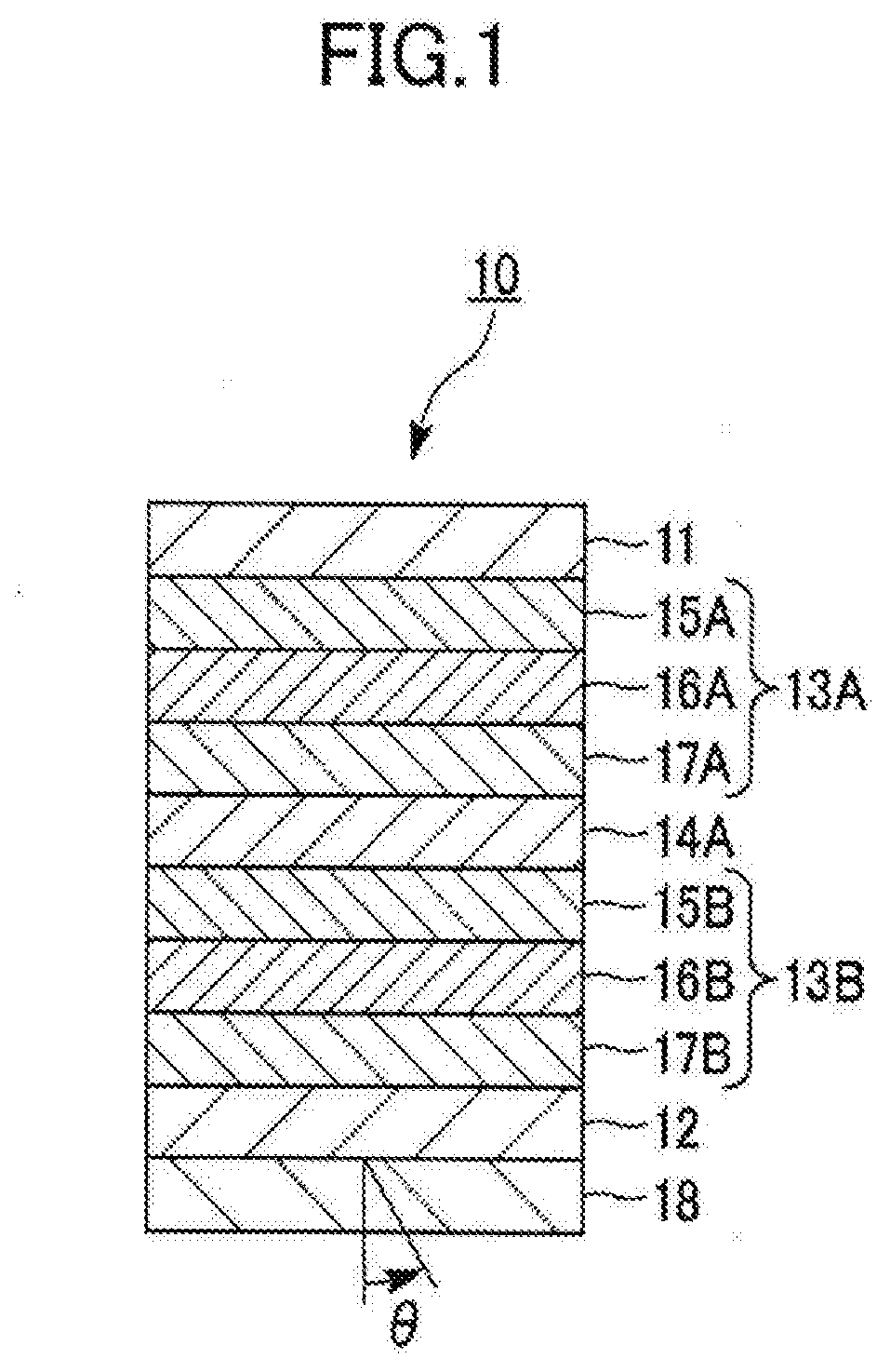
[0099]FIG. 1 is a cross-sectional view illustrating a schematic configuration of an organic EL device according to a first embodiment of the present invention.
[0100]As illustrated in FIG. 1, the organic EL device 10 of the embodiment has a structure in which multiple light emitting units 13A, 13B each including a light emitting layer made of at least an organic compound are stacked one on top of the other between a first electrode 11 and a second electrode 12 with a charge generating layer (CGL) 14A sandwiched between the light emitting units 13A, 13B. The organic EL device 10 is an organic EL device capable of providing white light through a substrate 18 adjacent to the second electrode 12 by causing the multiple light emitting units 13A, 13B to emit light.
[0101]Note that the organic EL device 10 of the embodiment may be an organic EL device capable of providing white light through a substrate adjacent to the first electr...
second embodiment
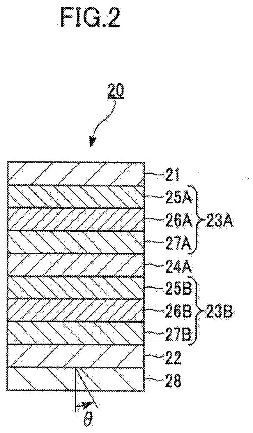
[0153]FIG. 2 is a cross-sectional view illustrating a schematic configuration of an organic EL device according to a second embodiment of the present invention.
[0154]As illustrated in FIG. 2, the organic EL device 20 of the embodiment has a structure in which multiple light emitting units 23A, 23B each including a light emitting layer made of at least an organic compound are stacked one on top of the other between a first electrode 21 and a second electrode 22 with a charge generating layer (CGL) 24A sandwiched between the light emitting units 23A, 23B. The organic EL device 20 is an organic EL device capable of providing white light through a substrate 28 adjacent to the second electrode 22 by causing the multiple light emitting units 23A, 23B to emit light.
[0155]Note that the organic EL device 20 of the embodiment may be an organic EL device capable of providing white light through a substrate adjacent to the first electrode 21.
[0156]The first light emitting unit 23A is a red / gree...
third embodiment
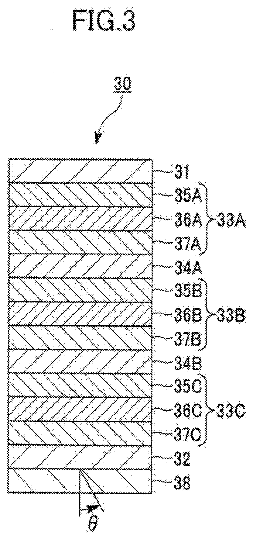
[0195]FIG. 3 is a cross-sectional view illustrating a schematic configuration of an organic EL device according to a third embodiment of the present invention.
[0196]As illustrated in FIG. 3, the organic EL device 30 of the embodiment has a structure in which multiple light emitting units 33A, 33B, 33C each including a light emitting layer made of at least an organic compound are stacked one on top of another between a first electrode 31 and a second electrode 32 with each of charge generating layers (CGL) 34A, 34B sandwiched between a corresponding pair of adjacent light emitting units. The organic EL device 30 is an organic EL device capable of providing white light through a substrate 38 adjacent to the second electrode 32 by causing the multiple light emitting units 33A, 33B, 33C to emit light.
[0197]Note that the organic EL device 30 of the embodiment may be an organic EL device capable of providing white light through a substrate adjacent to the first electrode 31.
[0198]The firs...
PUM
| Property | Measurement | Unit |
|---|---|---|
| color temperature | aaaaa | aaaaa |
| color rendering index | aaaaa | aaaaa |
| wavelength band | aaaaa | aaaaa |
Abstract
Description
Claims
Application Information
 - R&D
- Intellectual Property
- Life Sciences
- Materials
- Tech Scout
- Unparalleled Data Quality
- Higher Quality Content
- 60% Fewer Hallucinations
Browse by: Latest US Patents, China's latest patents, Technical Efficacy Thesaurus, Application Domain, Technology Topic, Popular Technical Reports.
© 2025 PatSnap. All rights reserved.Legal|Privacy policy|Modern Slavery Act Transparency Statement|Sitemap|About US| Contact US: help@patsnap.com


