Plasma display panel structure

a technology of plasma display panel and display panel, which is applied in the direction of discharge tube/lamp details, discharge tube main electrodes, gas-filled discharge tubes, etc., can solve the problems of adversely affecting the overall luminance and contrast ratio of the plasma display panel b>100, and achieve the enhancement of luminance and display contrast ratio, facilitate the coating of a light-shielding layer, and enhance the effect of luminance and contrast ratio

Inactive Publication Date: 2005-05-12
AU OPTRONICS CORP
View PDF7 Cites 14 Cited by
  • Summary
  • Abstract
  • Description
  • Claims
  • Application Information

AI Technical Summary

Benefits of technology

[0006] The present application describes a plasma display panel structure configured to provide enhanced luminance and display contrast ratio. In one embodiment, display cells in the plasma display panel are arranged in a delta structure. The delta structure of display cells facilitates the coating of a light-shielding layer around the boundary areas of displ

Problems solved by technology

Because the boundary area of each display cell is substantially aligned with the boundary area of adjacent display cells, the light from one di

Method used


Image

  • Plasma display panel structure
  • Plasma display panel structure
  • Plasma display panel structure

Examples


Embodiment Construction

)

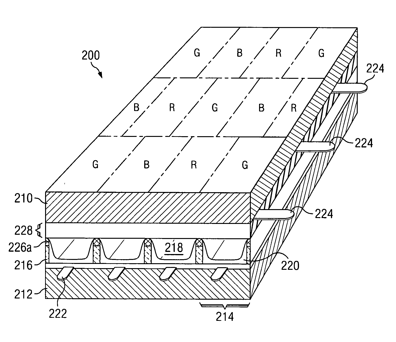
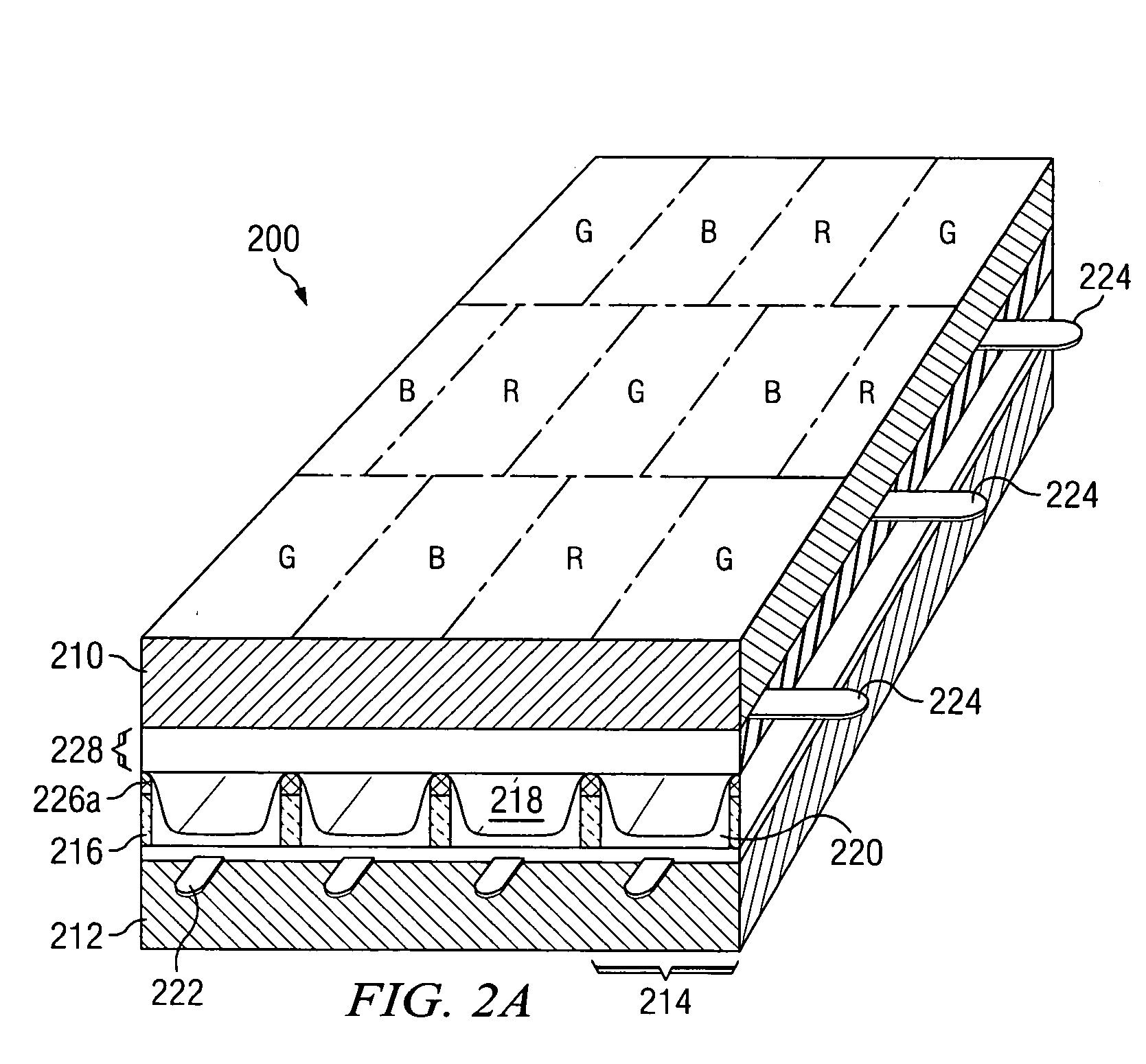
[0023]FIG. 2A is a perspective view of an exemplary plasma display panel 200 with display cells 214 arranged in a delta structure. The plasma display panel 200 includes a front substrate 210 and a rear substrate 212. In the present example, the front substrate 210 and the rear substrate 212 are made of glass. The front substrate 210 and the rear substrate 212 form display cells 214. Display cells 214 are delimited by partition walls 216. Each display cell 214 is coupled to at least one display electrode 224 and one address electrode 222. A gas discharge gap 218 is formed in each display cell 214. The inner surface of each display cell 214 is covered with a light-emitting layer 220. The light-emitting layer 220 can be made of a phosphorous-based material. A dielectric layer 228 separates display cells 214 from the front substrate 210.

[0024]FIG. 2B is a perspective view of an internal structure of the exemplary plasma display panel 200 of FIG. 2A. The gas discharge gap 218 in each d...


PUM


Abstract

The present application describes a plasma display panel structure with high contrast ratio and high luminance. In one embodiment, display cells in the plasma display panel are arranged in a delta structure. The delta structure of display cells enhances the luminance and contrast ratio of the plasma display panel. In some embodiments, a light-shielding layer is configured to selectively exclude display cells of one or more selected colors to enhance the color temperature of the plasma display panel.

Description

FIELD OF THE INVENTION [0001] The present invention generally relates to plasma display panels and, more particularly, to a plasma display panel with enhanced luminance and contrast ratio. DESCRIPTION OF THE RELATED [0002] Generally, plasma display panels are used as large screen displays. Typically, plasma display panels are flat and provide better image quality compared to cathode ray tube displays. Plasma display panels include display cells filled with a discharge gas. Each display cell is coated with a light-emitting layer typically made of a phosphorous-based material. To produce an image in the plasma display panel, an electric bias is applied to select one or more display cells. Upon receiving the electrical bias, the discharge gas in the selected display cell emits ultraviolet rays. When ultraviolet rays strike the light-emitting layer of the selected display cell, the light-emitting layer produces a visible color light. The color of the visible light depends upon the compo...

Claims


Application Information

Patent Timeline
IPC IPC(8): H01J17/16H01J11/02
CPCH01J11/12H01J2211/444H01J2211/365H01J11/44
Inventor WAN, SHIANG WENSU, YAO CHING
Owner AU OPTRONICS CORP
Why Eureka
Try Eureka