

LED plane light source lamp
- Summary
- Abstract
- Description
- Claims
- Application Information
AI Technical Summary
Benefits of technology
Problems solved by technology
Method used
Image

Examples
first embodiment
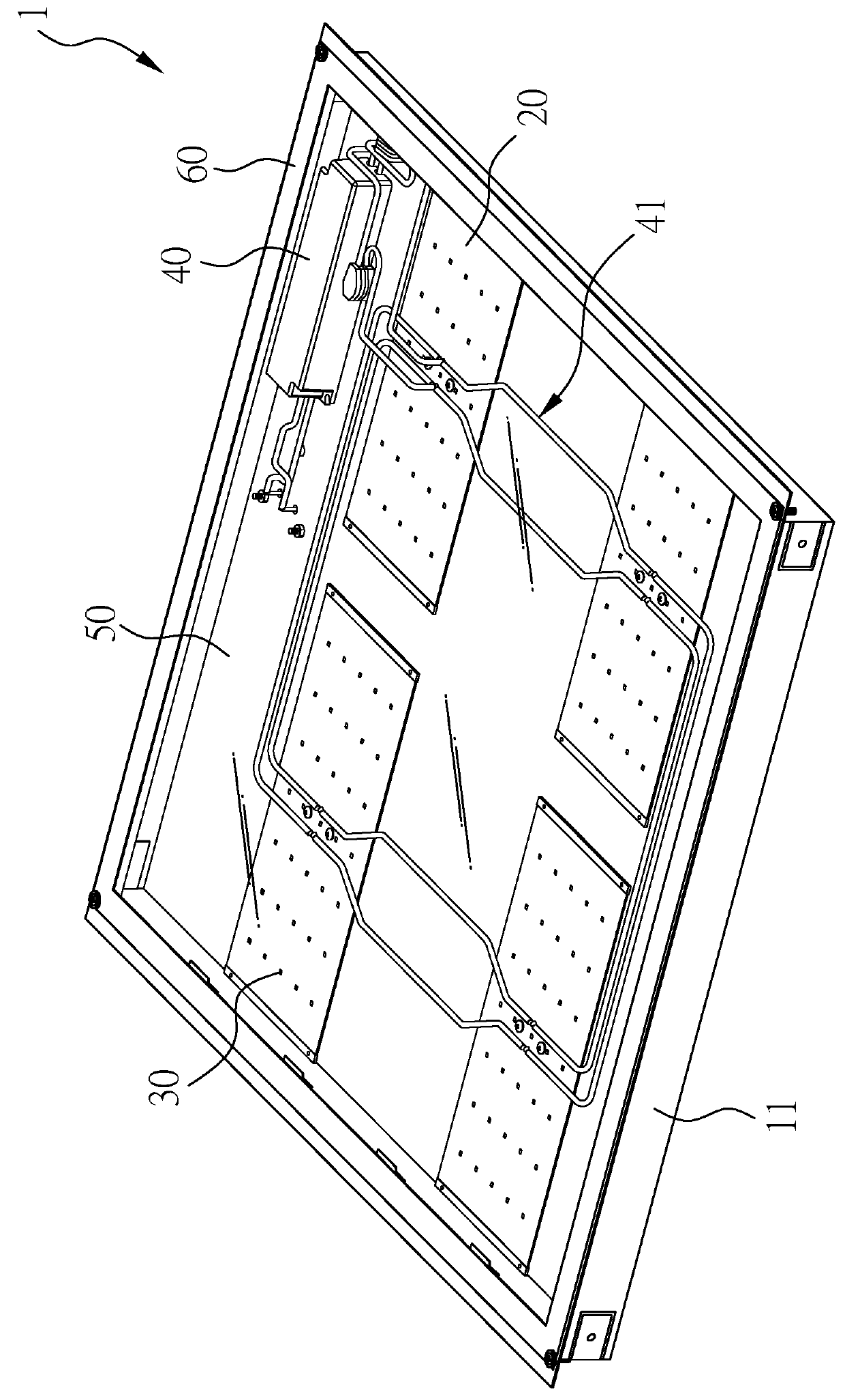
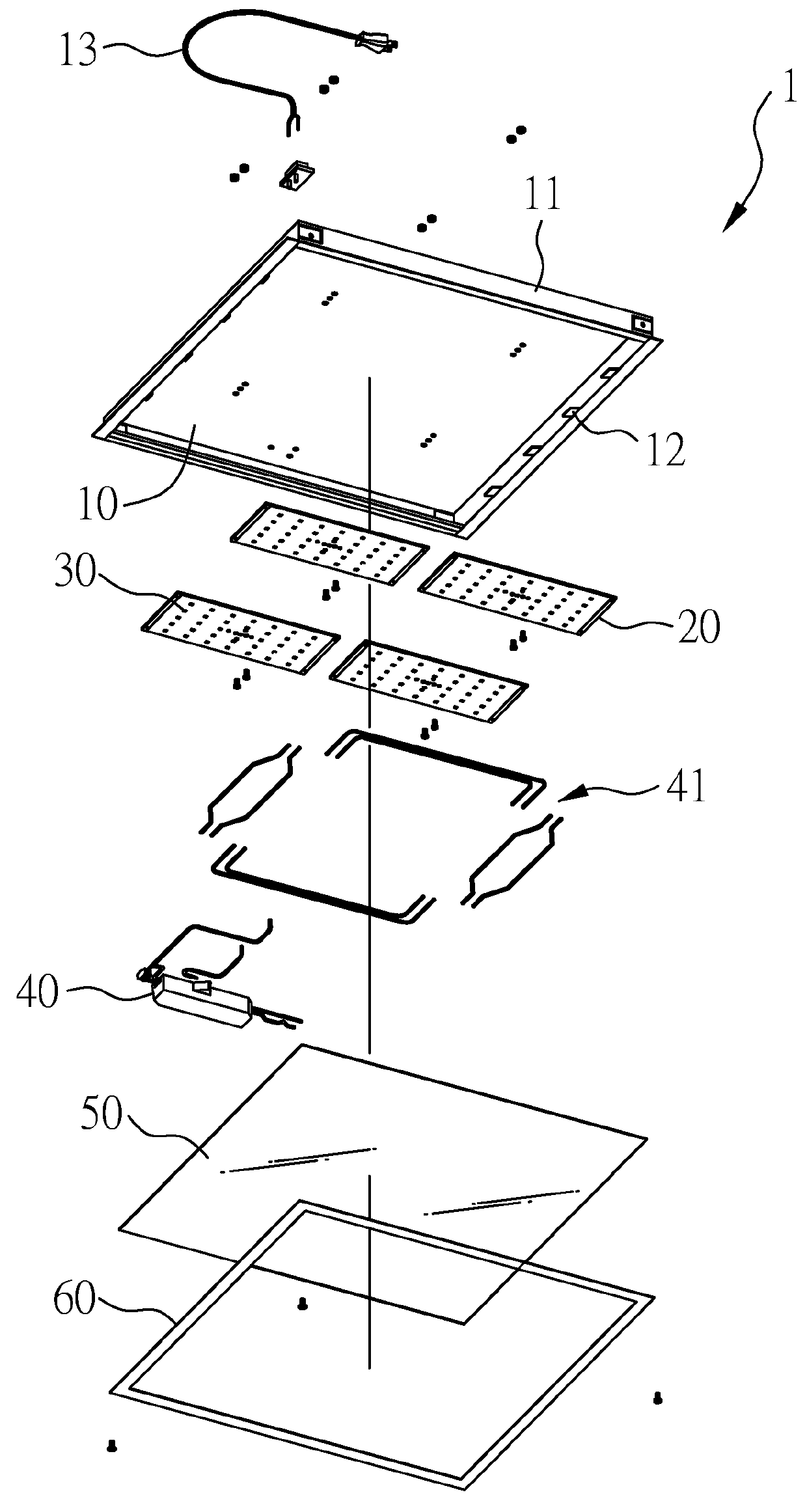
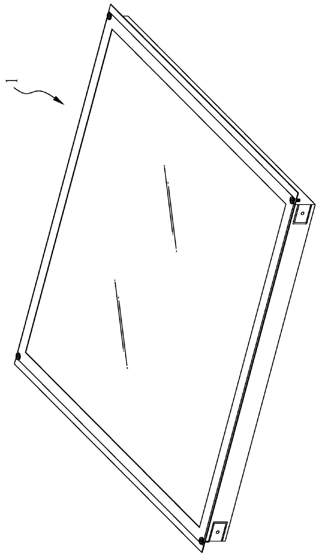
[0015]FIGS. 1 to 4 are a perspective view, an exploded view, a top perspective view and a bottom perspective view of a light emitting diode plane source lamp 1, respectively, according to a first embodiment of the present invention. References are made to FIGS. 1 to 4.
[0016]In this embodiment, the light emitting diode plane source lamp 1 mainly includes a substrate 10, four side plates 11, four circuit boards 20, a plurality of light emitting diodes 30, a power supplier 40 and a fogging film 50.
[0017]The substrate 10 is rectangular, so that it can be easily installed in a ceiling or a wall. The four side plates 11 are set on four sides of the substrate 10, respectively, and they are perpendicular to the substrate 10. The fogging film 50 is set on the four side plates 11 and opposite to the substrate 10. Therefore, the substrate 10, the four side plates 11 and the fogging film 50 form a container space.
[0018]Selectively, the setting of fogging film 50 can be achieved by setting a fra...
second embodiment
[0034]FIGS. 8 to 11 are a perspective view, an exploded view, a top perspective view and a bottom perspective view of a light emitting diode plane source lamp 1′, respectively, according to a second embodiment of the present invention. In this embodiment, the substrate 10 is longitudinally lengthened to contain two circuit boards 20. Except for the substrate 10, the components and the arrangement thereof are referred to the first embodiment.
[0035]One circuit board 20 having 35 light emitting diodes 30 only consumes electrical power of 5 Watts up to 10 Watts, preferably, 7.5 Watts, and in this embodiment, two circuit boards 20 each having 35 light emitting diodes 30 only consume electrical power of 15 Watts. It shows that the present invention saves more electrical power than the prior art does. The temperature of the circuit board is about 25° C., which is lower than the temperature of the prior art LED tube.
third embodiment
[0036]FIGS. 12 to 15 are a perspective view, an exploded view, a top perspective view and a bottom perspective view of a light emitting diode plane source lamp 1″, respectively, according to a third embodiment of the present invention. In this embodiment, the substrate 10 is longitudinally lengthened to contain three circuit boards 20. Except for the substrate 10, the components and the arrangement thereof are referred to the first embodiment.
[0037]In measurement, three circuit boards 20 each having 35 light emitting diodes 30 only consumes electrical power of 20 Watts. It shows that the present invention saves more electrical power than the prior art does. The temperature of the circuit board is about 25° C., which is lower than the temperature of the prior art LED tube.
[0038]In conclusion, the light emitting diode plane source lamp of the present invention can provide uniform plane source. In addition, in the present invention, it is noted that the fogging film 50 has a non-linear...
PUM
| Property | Measurement | Unit |
|---|---|---|
| Power | aaaaa | aaaaa |
| Height | aaaaa | aaaaa |
| Radiant flux | aaaaa | aaaaa |
Abstract
Description
Claims
Application Information