
Flexible display panel

a display panel and flexible technology, applied in the direction of identification means, semiconductor/solid-state device details, instruments, etc., can solve the problems of more difficult to realize narrow frames and narrow frames cannot be realized, and achieve the effect of reducing the number of scan lines in special-shaped cutout areas

Active Publication Date: 2021-01-12
WUHAN CHINA STAR OPTOELECTRONICS TECH CO LTD
View PDF10 Cites 0 Cited by
  • Summary
  • Abstract
  • Description
  • Claims
  • Application Information

AI Technical Summary

Benefits of technology

The patent is about a new design for reducing the number of scan lines in a special-shaped cutout area, which can lower the frame of the cutout area. The design involves using different metal materials for the scan lines in a first and second layer. By doing so, the number of scan lines in the cutout area can be reduced, resulting in a frame that is smaller and more efficient.

Problems solved by technology

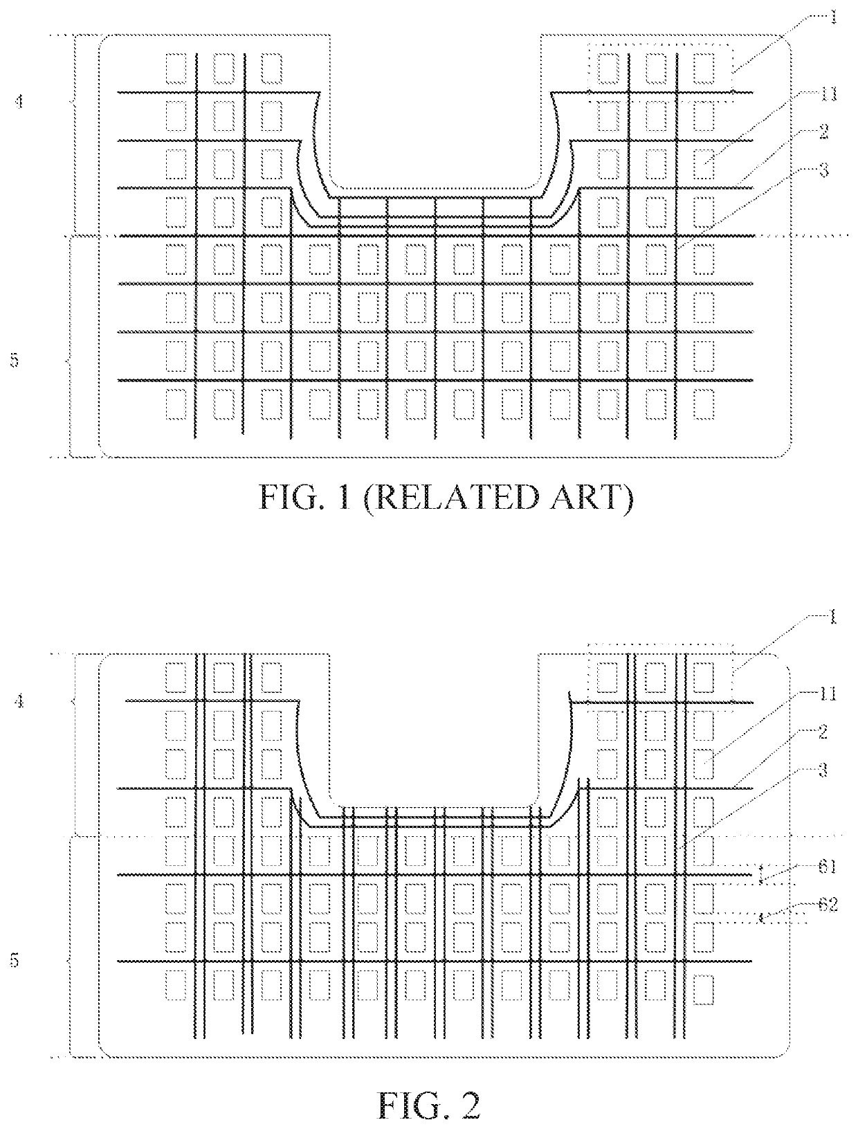
In the cutout area 4, the scanning lines 2 are deployed, which results in the boundary area of the special-shaped cutout become too large, so that the narrow frame cannot be realized.
The deeper the special-shaped cutout area 4, the more the scanning lines are needed, and it is more difficult to realize the narrow frame.

Method used


Image

  • Flexible display panel
  • Flexible display panel

Examples


embodiment 1

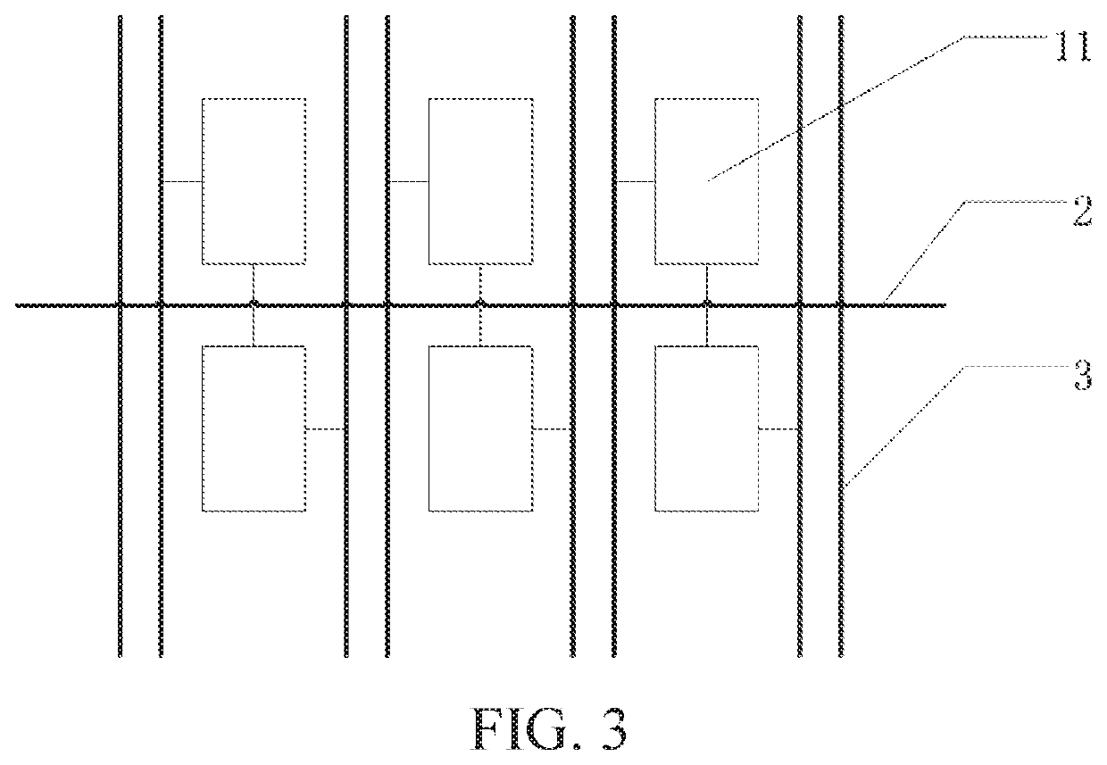
[0029]Referring to FIG. 2, the present disclosure provides a flexible display panel defined with a special-shaped cutout area 4 and a display area 5, comprising a substrate and a plurality of pixel structures 1, a scan line layer and a data line layer disposed on the substrate. The scan line layer comprises a plurality of scan lines 2, the data line layer comprises a plurality of data lines 3, and each of the pixel structures 1 comprises three sub-pixels 11.

[0030]The sub-pixels 11 are arranged in an array over the substrate, and the scan lines 2 and the data lines 3 are disposed in the sub-pixel array. A scan line 2 is disposed between every two rows of sub-pixels 11, and two data lines 3 are disposed between each column of sub-pixels 11.

[0031]A distance between the two rows of sub-pixels 11 disposed with the scan lines is the first distance 61, and a distance between the two rows of sub-pixels 11 not provided with the scan lines is the second distance 62. A length of the second dis...

embodiment 2

[0037]The flexible display panel structure in embodiment 2 is also defined with a special-shaped cutout area and a display area, which are substantially the same as the structures in embodiment 1. The same structure can be referred to the corresponding description in the embodiment 1, and are not described again. The main difference between these two embodiments is that a scan line is disposed between each row of sub-pixels and a data line is disposed between each column of sub-pixels in the display area in this embodiment.

example 3

[0038]The flexible display panel structure in embodiment 2 is also defined with a special-shaped cutout area and a display area, which are substantially the same as the structures in embodiment 1. The same structure can be referred to the corresponding description in the embodiment 1, and are not described again. The main difference between these two embodiments the display area in this embodiment comprises a normal area and a modified area. A scan line is disposed between every two rows of the two sub-pixels and two data lines are disposed between every column of the sub-pixels in the modified area, and a scan line is disposed between every row of the sub-pixels and a data line is disposed between every column of the sub-pixels in the normal area.

[0039]Furthermore, in other embodiments, a surface area of the modified area is smaller than a surface area of the display area.

[0040]Furthermore, in other embodiments, a surface area of the modified area is 10% to 90% of a surface area of...


PUM


Abstract

A flexible display panel is provided and defined with a special-shaped cutout area and a display area, including a substrate, and a plurality of pixel structures, a scan line layer, and a data line layer disposed above the substrate, wherein each of the plurality of the pixel structures includes three sub-pixels, and the scan line layer includes a plurality of scan lines, and the data line layer includes a plurality of data lines. The sub-pixels are arranged as an array over the substrate, and the scan lines and the data lines are disposed in the array of the sub-pixels. A scan line is disposed between every two rows of the sub-pixels and two data lines are disposed between every column of the sub-pixels in the special-shaped cutout area. Therefore, the frame of the special-shaped cutout area can be reduced to realize the narrow frame of the special-shaped cutout area.

Description

RELATED APPLICATIONS[0001]This application is a National Phase of PCT Patent Application No. PCT / CN2019 / 084331 having International filing date of Apr. 25, 2019, which claims the benefit of priority of Chinese Patent Application No. 201811446859.X filed on Nov. 29, 2018. The contents of the above applications are all incorporated by reference as if fully set forth herein in their entirety.FIELD AND BACKGROUND OF THE INVENTION[0002]The present application relates to display panel technologies, and more particularly to a flexible display panel.[0003]Presently, full-screen display has become trendy on the market, especially with the release of XIAOMI MIX2 and IPHONE X. Because the full-screen display is of wide concern by the market, various mobile phone manufacturers have launched their mobile phones having a full-screen display. For the purpose to place electronic components such as front cameras and sensors on the body, the screen will have a certain distance from the phone edge. Th...

Claims


Application Information

Patent Timeline
Patent Type & Authority Patents(United States)
IPC IPC(8): H01L27/32H01L27/12H01L23/498
CPCH01L27/124H01L23/4985H01L27/1218G09F9/301G09G3/20H01L23/13
Inventor ZHANG, JINGLILIAO, ZUOMINXUE, JINGFENG
Owner WUHAN CHINA STAR OPTOELECTRONICS TECH CO LTD
Learn More