Apparatus, systems and methods for oil and gas operations

a technology apparatus, applied in the field of apparatus, systems and methods for oil and gas operations, can solve the problems of compromising the original design of the christmas tree, complex and carefully designed christmas tree equipment, and avoiding deviations in the location of critical components

Active Publication Date: 2021-01-19
ENPRO SUBSEA
View PDF17 Cites 0 Cited by
  • Summary
  • Abstract
  • Description
  • Claims
  • Application Information

AI Technical Summary

Benefits of technology

[0003]There are a number of reasons why it is desirable to access a flow system in an oil and gas production system. In the context of this specification, the term “fluid intervention” is used to encapsulate any method which accesses a flow line, manifold or tubing in an oil and gas production, injection or transportation system. This includes (but is not limited to) accessing a flow system for fluid sampling, fluid diversion, fluid recovery, fluid injection, fluid circulation, fluid measurement and / or fluid metering. This can be distinguished from full well intervention operations, which generally provide full (or near full) access to the wellbore. Full well intervention processes and applications are often technically complex, time-consuming and have a different cost profile to fluid intervention operations. It will be apparent from the following description that the present invention has application to full well intervention operations. However, it is an advantage of the invention that full well intervention may be avoided, and therefore preferred embodiments of the invention provide methods and apparatus for fluid intervention which do not require full well intervention processes.
[0004]International patent application numbers WO00 / 70185, WO2005 / 047646, and WO2005 / 083228 describe a number of configurations for accessing a hydrocarbon well via a choke body on a Christmas tree.
[0005]Although a choke body provides a convenient access point in some applications, the methods of WO00 / 70185, WO2005 / 047646, and WO2005 / 083228 do have a number of disadvantages. Firstly, a Christmas tree is a complex and carefully-designed piece of equipment. The choke performs an important function in production or injection processes, and its location on the Christmas tree is selected to be optimal for its intended operation. Where the choke is removed from the choke body, as proposed in the prior art, the choke must be repositioned elsewhere in the flow system to maintain its functionality. This compromises the original design of the Christmas tree, as it requires the choke to be located in a sub-optimal position.
[0006]Secondly, a choke body on a Christmas tree is typically not designed to support dynamic and / or static loads imparted by intervention equipment and processes. Typical loads on a choke body in normal use would be of the order of 0.5 to 1 tonnes, and the Christmas tree is engineered with this in mind. In comparison, a typical flow metering system as contemplated in the prior art may have a weight of the order of 2 to 3 tonnes, and the dynamic loads may be more than three times that value. Mounting a metering system (or other fluid intervention equipment) on the choke body therefore exposes that part of the Christmas tree to loads in excess of those that it is designed to withstand, creating a risk of damage to the structure. This problem may be exacerbated in deepwater applications, where even greater loads may be experienced due to thicker and / or stiffer components used in the subsea infrastructure.
[0007]In addition to the load restrictions identified above, positioning the flow intervention equipment on the choke body may limit the access available to large items of process equipment and / or access of divers or remotely operated vehicles (ROVs) to the process equipment or other parts of the tree.
[0008]Furthermore, modifying the Christmas tree so that the chokes are in non-standard positions is generally undesirable. It is preferable for divers and / or ROV operators to be completely familiar with the configuration of components on the Christmas tree, and deviations in the location of critical components are preferably avoided.

Problems solved by technology

Full well intervention processes and applications are often technically complex, time-consuming and have a different cost profile to fluid intervention operations.
Firstly, a Christmas tree is a complex and carefully-designed piece of equipment.
This compromises the original design of the Christmas tree, as it requires the choke to be located in a sub-optimal position.
Secondly, a choke body on a Christmas tree is typically not designed to support dynamic and / or static loads imparted by intervention equipment and processes.
Mounting a metering system (or other fluid intervention equipment) on the choke body therefore exposes that part of the Christmas tree to loads in excess of those that it is designed to withstand, creating a risk of damage to the structure.
This problem may be exacerbated in deepwater applications, where even greater loads may be experienced due to thicker and / or stiffer components used in the subsea infrastructure.
In addition to the load restrictions identified above, positioning the flow intervention equipment on the choke body may limit the access available to large items of process equipment and / or access of divers or remotely operated vehicles (ROVs) to the process equipment or other parts of the tree.
Furthermore, modifying the Christmas tree so that the chokes are in non-standard positions is generally undesirable.
Another drawback of the prior art proposals is that not all Christmas trees have chokes integrated with the system; approaches which rely on Christmas tree choke body access to the flow system are not applicable to these types of tree.
When a sampling hydrocarbons during production operations, there are various technical challenges associated with obtaining a representative sample of hydrocarbons from the production flow.
However, Venturi devices in this application are sensitive to production flow.
If the Venturi is configured to operate at a peak production rate, then as the production rate drops, there may be insufficient pressure to drive the sampling circuit.
Conversely, if the Venturi is configured to operate at a reduced production rate, during periods of peak production, the sampling circuit may be overdriven, resulting in poor collection parameters and prevent representative samples from being collected.
However, differential pressures which are too high may result in freezing of the pipework and other flow system components.

Method used


Image

  • Apparatus, systems and methods for oil and gas operations
  • Apparatus, systems and methods for oil and gas operations
  • Apparatus, systems and methods for oil and gas operations

Examples


Embodiment Construction

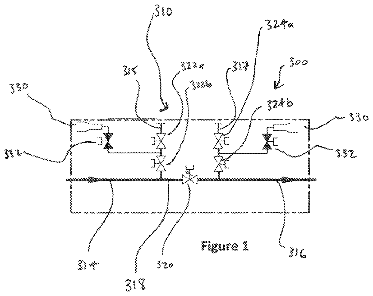
[0101]Referring firstly to FIG. 1, there is shown a valve apparatus according to a first embodiment of the invention. The valve apparatus, generally depicted at 300, is designed to be in conjunction with a subsea production system (not shown) and provides a flow access interface 310 to the subsea production system. In this embodiment, the valve apparatus comprises a first flow bore 314, a second flow bore 316, and first and second flow access bores 315, 317. The first and second flow bores 314, 316 are in fluid communication with the subsea production system. Disposed between the first and second flow bores 314, 316 is a bypass bore 318 comprising a flow control valve 320.

[0102]The flow access bores 315, 317 extend from the interface 310 to the flow bores 314, 316 and provide a fluid intervention path between the interface and the production system to which the valve apparatus is connected. In each of the flow access bores 315, 317 there is located a pair of isolation valves 322a, 3...


PUM


Abstract

A valve apparatus (400) for a flow system in a subsea oil and gas production installation and a method of use. The valve apparatus comprises an inlet for production flow from the subsea oil and gas production installation, an outlet for production flow, and a flow control valve (420) disposed between the inlet and the outlet. A first flow line (361) in communication with a sampling circuit is disposed between the inlet and the flow control valve, and a second flow line (362) in communication with a sampling circuit is disposed between the outlet and the flow control valve. The flow control valve is operable to be partially closed to create a pressure differential between the first and second flow lines, and thereby drive a production fluid into the sampling circuit.

Description

[0001]The present invention relates to apparatus, systems and methods for oil and gas operations, in particular to apparatus, systems and methods for fluid intervention in oil and gas production or injection systems. The invention has particular application to subsea oil and gas operations, and aspects of the invention relate specifically to sampling apparatus, systems and methods for fluid intervention in subsea oil and gas production and injection infrastructure.BACKGROUND TO THE INVENTION[0002]In the field of oil and gas exploration and production, it is common to install an assembly of valves, spools and fittings on a wellhead for the control of fluid flow into or out of the well. A Christmas tree is a type of fluid manifold used in the oil and gas industry in surface well and subsea well configurations and have a wide range of functions, including chemical injection, well intervention, pressure relief and well monitoring. Christmas trees are also used to control the injection o...

Claims


Application Information

Patent Timeline
Patent Type & Authority Patents(United States)
IPC IPC(8): E21B34/04E21B49/08E21B33/076
CPCE21B49/086E21B33/076E21B34/04E21B49/08
Inventor DONALD, IANREID, JOHN
Owner ENPRO SUBSEA
Why Eureka
Try Eureka