Drill insert

a drill insert and metal cutting technology, applied in the direction of cutting inserts, twist drills, manufacturing tools, etc., can solve the problems of becoming more brittle, more susceptible to fracture and breakage, and achieve the effect of high-efficiency drilling and borehole creation

Active Publication Date: 2021-08-31
SANDVIK INTELLECTUAL PROPERTY AB
View PDF19 Cites 0 Cited by
  • Summary
  • Abstract
  • Description
  • Claims
  • Application Information

AI Technical Summary

Benefits of technology

[0006]It is an objective of the present invention to provide an insert for a drill tool configured to create short chip fragment lengths and to specifically avoid the creation of chips formed as tightly curled balls or long helical strips. Accordingly, it is the general objective to provide a drill insert for cutting metal enabling highly efficient drilling and borehole creation.
[0007]It is a specific objective to provide an insert for a drill tool configured to facilitate workpiece chip fracture and breaking as the chip is formed at the insert cutting region. Accordingly, it is an objective to facilitate rearward axial transport of the chip fragments from the as-formed borehole to prevent blockage or clogging of the bore that would otherwise hinder continued axial advancement of the drill tool. It is a further specific objective to provide an insert to facilitate chip breakage without weakening the insert with regard to wear and fatigue encountered during cutting. It is a yet further objective to provide an insert that is not detrimental to drilling stability and particularly does not destabilise a desired smooth rotational motion of the drill tool.
[0008]The objectives are achieved by providing a cutting insert configured firstly to facilitate the creation of the chip that is more susceptible to fracture and breakage and secondly to encourage the as-formed chip to break immediately or shortly after it is created from the workpiece. This is advantageous to minimise chip size and accordingly facilitate chip evacuation from the as-formed borehole. The objectives are achieved specifically via an insert having a raised or recessed chip disruptor (alternatively referring to herein as a chip breaker) positioned at a rake face at the insert immediately behind the cutting edge. The chip disruptor is accordingly configured to provide an obstruction positioned within the path of the as-created chip to induce mechanical stress to the chip and encourage it to break. The objectives are achieved further by providing a chamfer at the leading portion of the chip disruptor, located at the region of the cutting edge of the insert. The chamfer may be considered to represent an intersection of the adjoining rake face and clearance face and is defined relative to a remainder of the cutting edge (at one or both sides of the chip disruptor) that may be considered to be non-chamfered and to have a different shape profile. That is, and preferably, the remainder of the cutting edge (defined by the intersection of the rake face and the clearance face) may be considered sharp, angled or acute relative to that portion of the cutting edge within the region of the chip disruptor that is chamfered (alternatively termed bevelled). The chamfer comprises an intersection surface (being a transition region between the rake face and the clearance face) that may be substantially planar and aligned transverse the rake face and the clearance face. Optionally, the intersection surface may be curved comprising one or a plurality of radii of curvature in a plane perpendicular to a length of the cutting edge as defined in widthwise direction across the insert between a first lateral side and a second lateral side.

Problems solved by technology

Accordingly, the chip when formed is heated to a greater extent at the region of the chip disruptor and accordingly becomes more brittle and is therefore more susceptible to fracture and breakage.

Method used


Image

  • Drill insert
  • Drill insert
  • Drill insert

Examples


Embodiment Construction

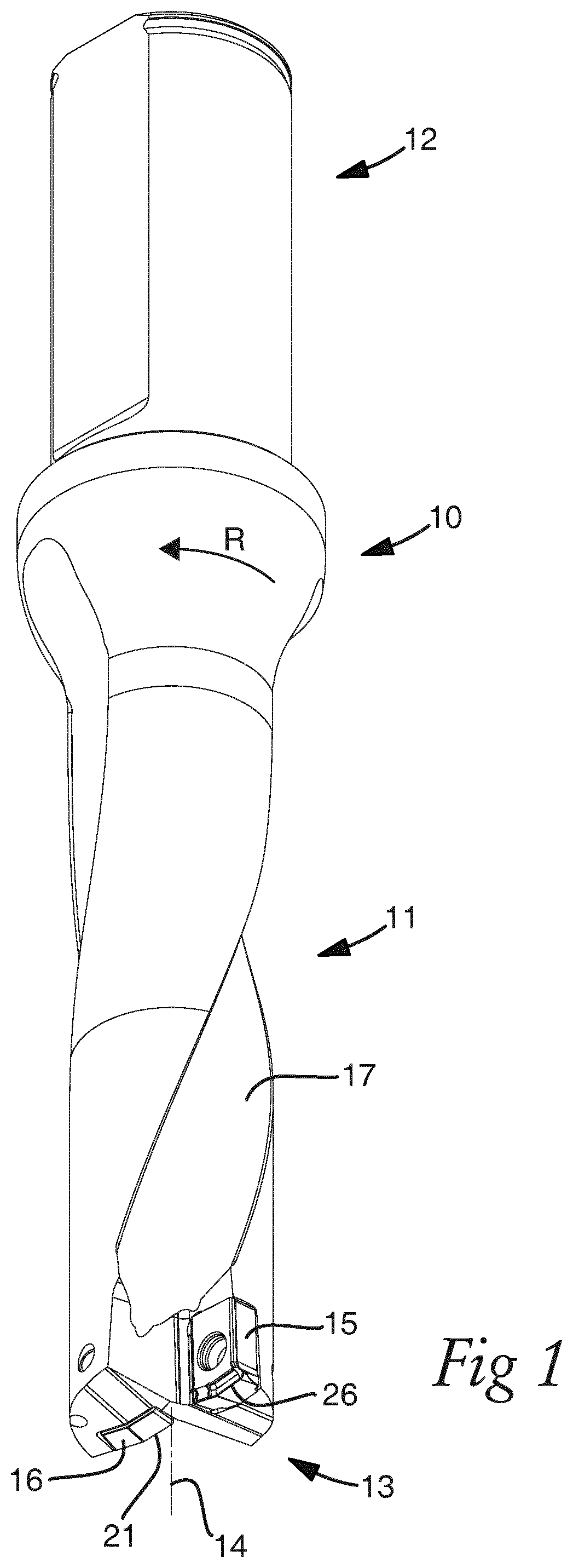
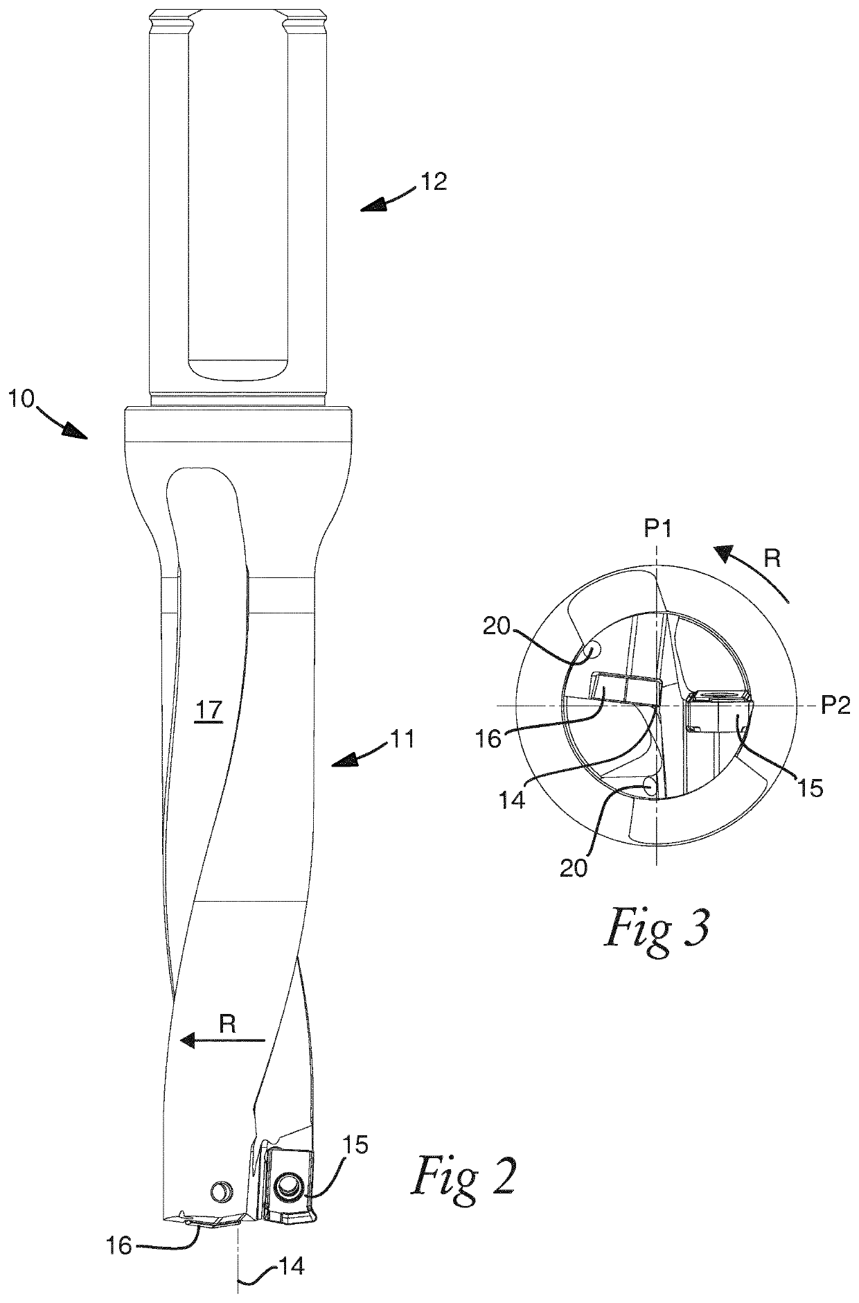
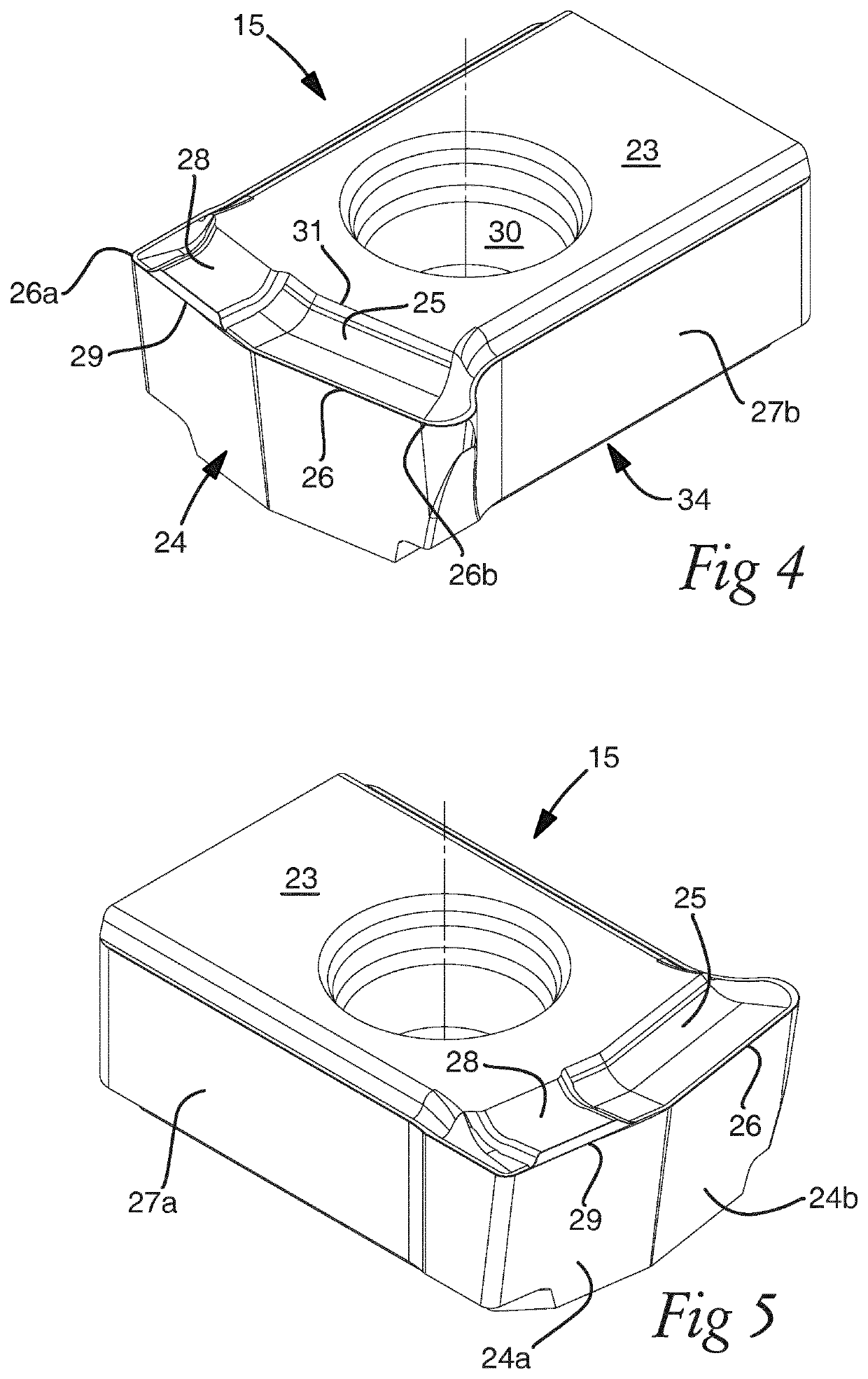
[0041]Referring to FIGS. 1 and 2, an indexable-insert drill tool specifically adapted for cutting metal comprises a drill body 10 having an axially rearward shank to mount the drill body 10 within a drilling machine and an axially forward shaft 11 having a cutting end 13. Shaft 11 comprises a pair of radially opposed chip flutes 17 extending axially and helically around a central longitudinal axis 14 of drill body 10 from cutting end 13 towards a rearward end of shaft 11. Referring to FIG. 3, a pair of bores 20 extend axially through drill body 10 to provide delivery of a flushing fluid. A pair of abrasion resistant cutting inserts are mounted at shaft cutting end 13 that include specifically a central insert 16 and a peripheral insert 15. Each insert 15, 16 comprises a bore 30 (illustrated for the peripheral insert 16 within FIGS. 4 to 6) to receive a mounting screw (not shown) for attachment to the drill shaft 11. Central insert 16 comprises a leading cutting edge 21 and periphera...


PUM

PropertyMeasurementUnit
angleaaaaaaaaaa
angleaaaaaaaaaa
angleaaaaaaaaaa

Abstract

A metal cutting drill insert for a drill tool having a chip disruptor provided at a rake face. The chip disruptor is further configured with a chamfer at a leading cutting edge region to increase cutting resistance and facilitate chip breakage.

Description

RELATED APPLICATION DATA[0001]This application is a § 371 National Stage Application of PCT International Application No. PCT / EP2018 / 072894 filed Aug. 24, 2018 claiming priority to EP17189610.3 filed Sep. 6, 2017.FIELD OF INVENTION[0002]The present invention relates to a metal cutting drill insert for a drill tool having a chip disruptor provided at a rake face of the insert configured to facilitate chip breaking during drilling and create small chip fragments.BACKGROUND ART[0003]Rotatable drill tools find specific application for workpiece processing in addition to general cutting and milling tools. Conventionally, an indexable insert drill tool includes at least two separate inserts in which a central insert is mounted at an axial centre of the tool and a peripheral insert represents a radially outermost portion of the cutting region. Accordingly, during rotation of the tool the central insert, being axially forward relative to the peripheral insert, creates a ring-shaped groove i...

Claims


Application Information

Patent Timeline
Patent Type & Authority Patents(United States)
IPC IPC(8): B23B51/02B23B51/04
CPCB23B51/048B23B2200/242B23B2251/122B23B2251/48B23B2251/50Y10T407/245Y10T408/9097B23B51/00B23B51/04
Inventor CARLBERG, HAKANYAH, FRITZ ALUM
Owner SANDVIK INTELLECTUAL PROPERTY AB
Why Eureka
Try Eureka